
I. Overview
In modern industrial automation control systems, inverters play an extremely crucial role. The ATV630 series inverters launched by Schneider Electric are widely used in fields such as fans, pumps, and compressors, offering energy efficiency, flexible control, and extensive communication capabilities. However, during actual use, users may occasionally encounter a fault message on the screen indicating “Safety Function Error,” often accompanied by a status display of “STO,” indicating that the inverter is in a safe shutdown state.
This article provides a detailed analysis of the meaning of this error, its possible causes, wiring considerations, and practical methods for troubleshooting and resolving the fault.
II. Fault Meaning Analysis
On the ATV630 inverter, the “Safety Function Error,” or SAFF (Safety Function Fault), is a type of fault related to the STO (Safe Torque Off) safe shutdown function.
2.1 Overview of STO Function
STO (Safe Torque Off) is a safety function compliant with the IEC 61800-5-2 standard. Its primary role is to quickly disconnect the motor torque by shutting off the power output to the motor without cutting off the main power supply of the inverter.
2.2 Meaning of SAFF Fault
According to Schneider’s official manual, the specific definitions and possible causes of SAFF (safety function error) are as follows:
Possible Causes:
- Inconsistent states (high/low) of the STOA and STOB inputs for more than 1 second;
- Debounce time timeout;
- Internal hardware failure (modules related to safety functions).
Solutions:
- Check the wiring of the STOA and STOB digital inputs;
- Verify that jumpers are reliably connected;
- Contact Schneider’s official technical support if necessary;
- Clear the fault by performing a power reset.
III. Wiring Principles and Common Error Analysis
The STO function of the ATV630 typically uses terminals “STOA” and “STOB” to receive 24V inputs. Both ports must be at a high level simultaneously for the inverter to operate.
3.1 Standard Wiring Method
STOA ←→ 24VDC
STOB ←→ 24VDC
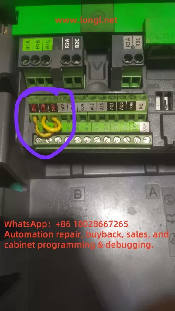
If the safety function is not used, “STOA” and “STOB” can be connected to “24V” respectively using short jumpers on the terminal block.
For example, in the picture you uploaded, the yellow jumpers connect “STOA→24V” and “STOB→24V,” which is theoretically correct.
3.2 Common Wiring Errors
- Connecting only one STO port (e.g., only STOA):
This leads to inconsistent states between the two, triggering the SAFF. - Loose or poor contact wiring:
Loose plugs, oxidation, or insufficient tightening can cause intermittent faults. - Incorrect jumper placement or use of non-industrial-grade wires:
This can result in high-frequency interference or open circuits in the wiring.
IV. Detailed Troubleshooting and Resolution Steps
Step 1: Check STO Wiring
- Turn off the power and open the terminal cover;
- Verify that both STOA and STOB are connected to 24V and ensure reliable connections;
- If the safety circuit is not used, short-circuit “STOA” and “STOB” using industrial-grade copper wires;
- Use a multimeter to measure the voltage of STOA and STOB relative to ground to confirm it is around 24V.
Step 2: Observe Parameter Status
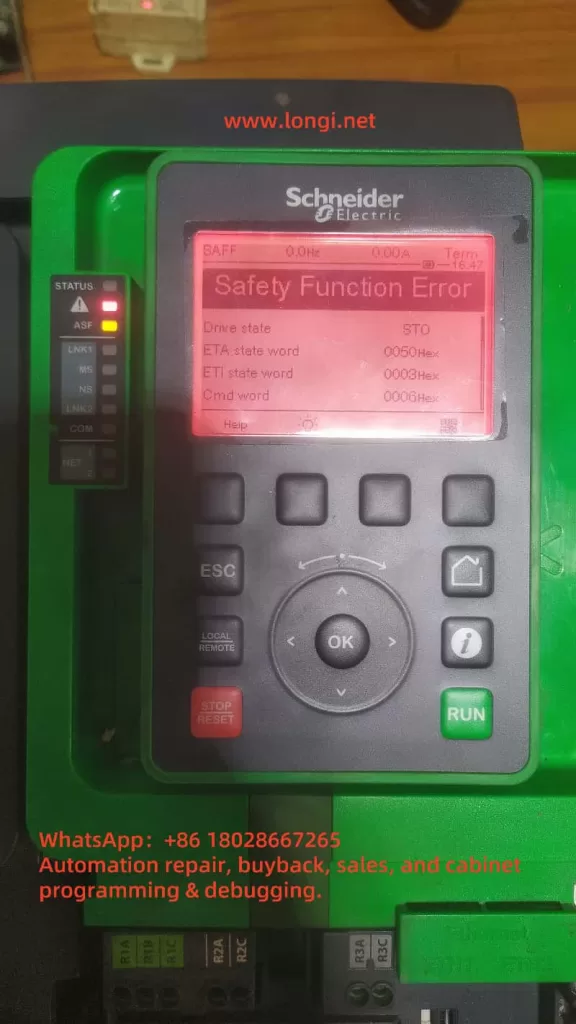
From the current control panel screenshot:
- ETA state word = 0x0050
- ETI state word = 0x0003
- Cmd word = 0x0006
- Drive state = STO
This indicates that the inverter has detected that the STO signal is not satisfied, preventing it from running.
Step 3: Fault Clearance Method
According to the manual, SAFF-type faults must be cleared by power cycling:
- Disconnect all main and control power supplies;
- Wait 15 minutes for the DC bus capacitors to fully discharge;
- Ensure correct wiring before reapplying power;
- Press the “STOP/RESET” button or use the rP parameter to restart the product;
- The fault should be cleared. If it persists, consider hardware issues or the use of an external safety circuit mode.
V. Extended Analysis: Is Enhanced Safety Function Enabled?
In certain applications, enhanced safety function modules (such as safety relays, Pilz, Sick, etc.) may be enabled, requiring STOA and STOB to be closed through these certified devices. If you have enabled “safety module enable (e.g., parameters such as SDI, IFSB, etc.),” the following situations may occur:
- The wiring appears correct, but the inverter’s internal logic judges it as illegal;
- The safety circuit must be closed within a specific time window; otherwise, a timeout will occur.
Check Parameters
Access the menu via the graphic terminal:
[Full Menu] → [Input/Output Configuration] → [Safety Function Allocation]
Check whether parameters such as “STO Input Allocation” and “Fault Reset Allocation” are controlled by external signals.
VI. Practical Suggestions and Summary
- When using default jumpers, ensure:
- Use a dual-core yellow wire to jump STOA and STOB to 24V;
- Ensure good contact, no oxidation, and no broken strands;
- Avoid cross-wiring with other I/Os.
- When enabling safety functions, it is recommended to configure:
- Use external safety modules compliant with PLe/SIL3 levels;
- Use example wiring diagrams provided by Schneider to avoid logical confusion;
- Configure digital inputs to monitor the status of the safety circuit (e.g., DI5/DI6 to monitor STO feedback).
- Fault clearance sequence:
- Eliminate the root cause of the fault;
- Ensure correct wiring;
- Perform a RESET or power cycle;
- Check whether “Fault Reset” and “STO Configuration” are activated in the menu.
VII. Conclusion
Although the “Safety Function Error” is a common protection mechanism in the ATV630 series, its underlying principle is to protect equipment and personnel safety. Understanding its working mechanism and control logic is crucial. Proper handling of STO ports and parameter configuration is the basic prerequisite for ensuring the safe operation of the equipment.
Through the systematic explanation in this article, readers should now be able to independently address such issues, quickly locate and accurately resolve them, and avoid situations where equipment cannot operate due to “STO false alarms.”