
1. System Overview
Constant pressure water supply technology is widely used in modern industrial and civil water systems for efficient and energy-saving operation. This project uses the Milan M5000 inverter as the control core, combined with the YTZ-150 potentiometric remote pressure gauge, to construct a closed-loop constant pressure control system. It enables automatic adjustment of a single water pump to ensure the outlet pressure remains stable within the set range.
The system features low cost, easy maintenance, and fast response, making it suitable for small water supply systems, factory cooling water circulation, boiler water replenishment, and more.
2. Main Hardware and Functional Modules
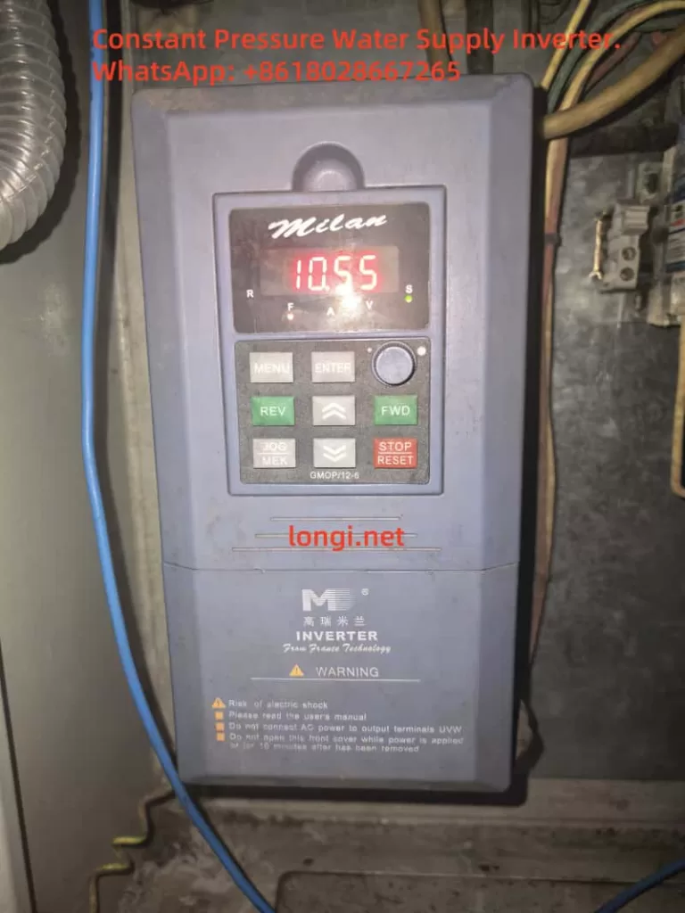
1. Inverter: Milan M5000 Series
- Built-in PID controller
- Supports multiple analog inputs (0-10V, 0-5V, 4-20mA)
- Provides +10V power output terminal for sensor power supply
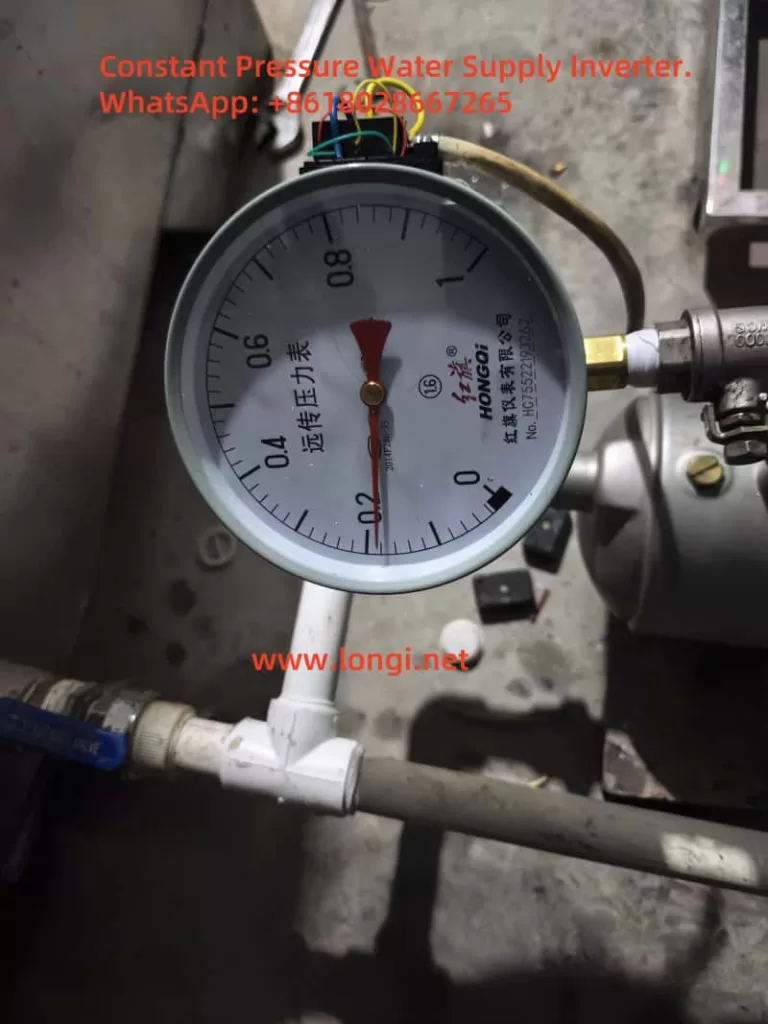
2. Pressure Sensor: YTZ-150 Potentiometric Remote Pressure Gauge
- Resistive output with a range of approx. 3–400Ω
- Rated working voltage ≤6V, but 10VDC tested in practice with stable long-term operation
- Outputs a voltage signal (typically 0–5V) varying with pressure via a voltage divider principle
3. Control Objective
- Adjust pump speed using the inverter to maintain constant pipe pressure
- Increase frequency when pressure drops, and decrease when pressure exceeds the setpoint to save energy
3. Wiring and Jumper Settings
1. 3-Wire Sensor Wiring (Tested with 10V)
| Sensor Wire | Function | Inverter Terminal |
|---|---|---|
| Red | +10V supply | Connect to +10V |
| Green | Ground (GND) | Connect to GND |
| Yellow | Signal output | Connect to VC1 input |
2. Analog Input Jumper JP8
- Default: 1–2 connected, indicating 0–10V input
- Keep the default setting in this project (no need to switch to 2–3)
4. PID Parameter Settings (Based on Field Use)
| Parameter | Description | Value | Note |
|---|---|---|---|
| P7.00 | Enable closed-loop control | 1 | Enable PID control |
| P7.01 | Setpoint source | 0 | Digital input from panel |
| P7.02 | Feedback source | 0 | VC1 analog input (0–10V) |
| P7.05 | Target pressure value (%) | 30.0 | Corresponds to 0.3MPa if P7.24=1.000 |
| P7.07 | Feedback gain | 1.00 | Linear scaling factor for feedback |
| P7.10 | PID control structure | 1 | Proportional + integral control |
| P7.11 | Proportional gain | 0.50 | Recommended initial value |
| P7.12 | Integral time constant | 10.0 | In seconds |
| P7.24 | Pressure sensor range (MPa) | 1.000 | 1.000 MPa full-scale |
| P1.19 | Maximum voltage input | 5.00 | Matched to 0–5V signal range |
5. Sleep Function Configuration
To enable energy saving when there is no pressure demand, the inverter can be configured to sleep:
| Parameter | Description | Value | Note |
|---|---|---|---|
| P7.19 | Wake-up threshold | 0.001 | Minimum pressure to resume operation (MPa) |
| P7.20 | Sleep threshold | 1.000 | Enter sleep mode above this value (MPa) |
| P7.23 | Constant pressure mode | 1 | One-pump control mode |
6. PID Tuning Guidelines
- After starting the system, observe pressure fluctuations:
- If large oscillations, reduce P7.11 (proportional gain)
- If sluggish response, reduce P7.12 (integral time)
- Aim to maintain output pressure within ±2% of the P7.05 set value
- Ensure return pipes have damping to prevent sudden pressure spikes
7. Key Considerations
- Keep JP8 jumper at default 1–2 for 0–10V input
- YTZ-150 sensor has been tested with 10V power supply and works stably
- Ensure proper grounding (PE terminal) to avoid PID interference from common-mode noise
- If feedback signal is noisy, add a filter capacitor (0.1–0.47μF) between VC1 and GND
8. Conclusion
With this design, the Milan M5000 inverter combined with the YTZ-150 pressure sensor delivers a cost-effective and reliable constant pressure control solution for water systems. The inverter’s built-in PID control simplifies implementation compared to external PLCs and offers strong performance with minimal tuning. As long as power supply, signal matching, and grounding are properly managed, the system achieves excellent closed-loop control stability.