
(1) Hardware Preparation & Network Setup
- Ethernet Module Installation: The ATV310 VFD does not include a built-in Ethernet port. To enable Modbus TCP over Ethernet, install an optional communication module such as the VW3A3616, which provides an RJ45 interface. Ensure the module is properly mounted and securely inserted into the option slot on the drive.
- Connecting the Network: Connect the VFD’s Ethernet port directly to your PC using a standard Ethernet cable, or connect both to the same switch. Configure your PC’s Ethernet interface to be in the same subnet—for example, assign it an IP like
192.168.0.10with subnet mask255.255.255.0. Disable firewalls to avoid communication issues. - Initial IP Setup via HMI Panel: If this is the first time using the Ethernet module, its IP address may default to
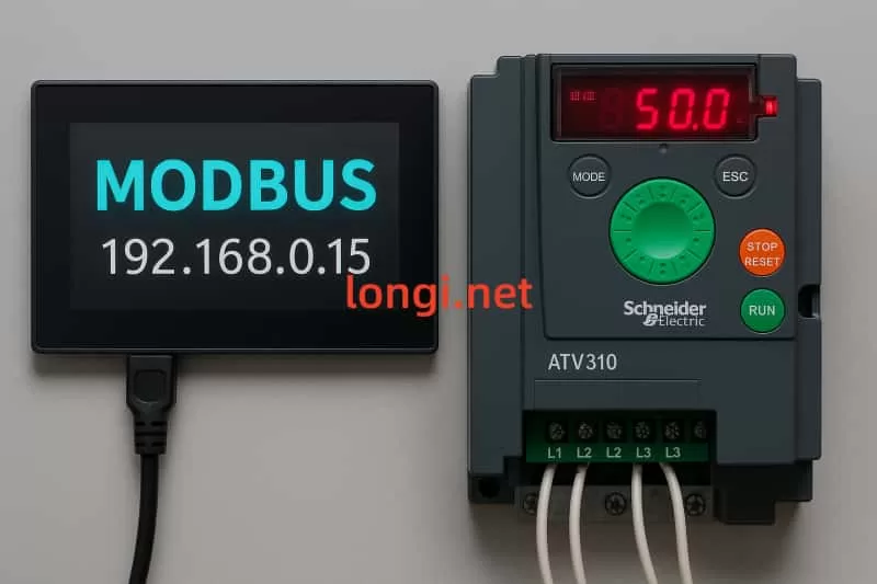
0.0.0.0, awaiting DHCP. Since you are using static IPs, enter the ATV310’s local HMI panel, navigate to the “Communication (COM-)” → “Ethernet (EtH-)” menu, set IP Mode to “Manual”, and configure a temporary IP (e.g.,192.168.0.15) with the appropriate subnet mask. If there’s no router, set the gateway to0.0.0.0. After setting, power cycle the VFD to apply the changes.

(2) Connecting to the ATV310 in SoMove
- Launch SoMove: Ensure the SoMove software is installed along with the DTM driver package compatible with the ATV310 (usually compatible with ATV31/ATV312 profiles). Open SoMove and start a new project or open an existing one.
- Set Up Communication:
- Click “Edit Connection/Scan” and choose Modbus TCP as the connection type.
- Click the advanced settings (gear icon), then under the “Scan” tab, choose Single Device, enter the temporary IP (e.g.,
192.168.0.15) and slave address (default is 1). - Apply and save the configuration.
- Scan and Connect: From the main screen, click “Scan”. If the IP and settings are correct, the VFD will be detected. Double-click it to establish the connection and load parameters.
(2) Setting the Static IP Address
Once connected, go to the Communication menu in the device parameter tree, then open the Ethernet (EtH-) submenu. Configure the following:
- IP Mode (
IpM): Set to Manual (0) to disable DHCP. - IP Address (
IPC1–IPC4): Set the 4 bytes individually. For example, to set192.168.0.15, enterIPC1=192,IPC2=168,IPC3=0,IPC4=15. - Subnet Mask (
IPM1–IPM4): Use a typical mask such as255.255.255.0(i.e.,IPM1=255,IPM2=255,IPM3=255,IPM4=0). - Gateway (
IPG1–IPG4): If you’re not using routing, set it to0.0.0.0. - Ethernet Protocol (
EthM): Ensure it is set to0for Modbus TCP (not Ethernet/IP).
Parameter Summary:
| Parameter Code | Function | Recommended Setting |
|---|---|---|
IpM (IP Mode) | IP acquisition method | 0 = Manual (disable DHCP) |
IPC1~IPC4 | IP address | e.g., 192.168.0.15 |
IPM1~IPM4 | Subnet mask | e.g., 255.255.255.0 |
IPG1~IPG4 | Gateway address | e.g., 192.168.0.1 or 0.0.0.0 |
EthM (Protocol) | Modbus TCP or Ethernet/IP | 0 = Modbus TCP |
Once settings are applied, write them to the drive and power cycle the VFD to activate the new static IP address.
(4) Verifying the Configuration
- Ping Test: From your PC, use the
pingcommand to check if the VFD responds to the new IP address (e.g.,ping 192.168.0.15). A successful response confirms network connectivity. - Reconnect in SoMove: Update the connection settings in SoMove with the new static IP and reconnect. You should be able to scan, access parameters, and monitor status.
- Check Ethernet Module LEDs: A solid green light typically indicates normal status. Blinking or red lights may indicate wiring errors, IP conflicts, or module faults.
- Modbus Communication Test: If integrating with an HMI or master software, send basic Modbus commands (e.g., reading frequency or writing speed setpoints) to ensure the VFD communicates correctly over Modbus TCP.
Conclusion
By following the above procedure, each ATV310 VFD can be configured with a unique static IP and operate reliably over an Ethernet network using Modbus TCP. This setup is especially effective in systems where communication is directly between an HMI and multiple drives, eliminating the need for a PLC. Proper IP planning, secure connections, and careful testing will ensure a stable and responsive network.