1. Introduction
In industrial automation control systems, inverters serve as the core equipment for motor drive, and their stability directly impacts the continuous operation of production lines. The Yaskawa H1000 series inverter, renowned for its high-precision vector control, rich functional expansion, and reliable hardware design, is widely used in scenarios such as fans, pumps, conveyor belts, and machine tools. However, in practical maintenance, the OPE04 fault (Motherboard Replacement Detection Fault) is one of the most common issues encountered by technicians—it can be triggered by either actual motherboard replacement or hardware contact failures/system false alarms. If mishandled, this fault may render the inverter unable to start normally, even affecting the efficiency of the entire production line.
This article delves into the essence of the OPE04 fault, hardware logic, and software mechanisms to provide technicians with scenario-based troubleshooting processes, preventive maintenance strategies, and practical case validations. The goal is to help technicians quickly locate issues, standardize operations, and ensure the inverter returns to stable operation.
2. Definition and Triggering Mechanism of OPE04 Fault
2.1 Official Interpretation of the Fault Code
According to the Yaskawa H1000 series inverter manual, OPE04 stands for “Board Replace Detect” (Motherboard Replacement Detection). Its core meaning is: The inverter’s control system detects a change in the control motherboard and requires an initialization operation to confirm the motherboard replacement status.
In simple terms, this is a “self-protection mechanism” of the inverter—the control motherboard is the “brain” of the inverter, storing user-defined parameters (e.g., motor rated power, acceleration/deceleration time, vector control parameters), operation logic (e.g., V/F curve, PID adjustment), and communication configurations (e.g., Modbus, Profibus). When the motherboard is replaced, the default parameters of the new motherboard may conflict with the original system parameters. Without “confirmation,” the inverter cannot guarantee operational consistency, so it triggers the OPE04 fault to force the user to complete initialization.
2.2 Triggering Scenarios for OPE04 Fault
The OPE04 fault is triggered in two categories: active scenarios and passive scenarios:
- Active Scenario: The user proactively replaces the control motherboard due to damage (e.g., capacitor breakdown, chip burnout) or functional upgrades (e.g., replacing with a motherboard supporting a higher communication protocol).
- Passive Scenario: No proactive motherboard replacement occurs, but the system falsely detects a “motherboard replacement” due to hardware contact failures (e.g., loose motherboard connectors, oxidation) or motherboard firmware abnormalities (e.g., program runaway).
3. Hardware Root Causes of OPE04 Fault: The “Core Status” and Replacement Specifications of the Control Motherboard
3.1 Functions and Structure of the Control Motherboard
The control motherboard (usually marked as the “CPU board”) of the Yaskawa H1000 inverter is the control center of the entire system. Its core components include:
- CPU Chip: Responsible for calculating control algorithms (e.g., vector control, PID adjustment) and processing user commands (e.g., start/stop, frequency setting).
- Memory Chips: Divided into non-volatile memory (e.g., EEPROM, stores user parameters) and volatile memory (e.g., RAM, stores runtime data).
- Interface Circuits: Connects the power board, driver board, operation panel, and external devices (e.g., sensors, PLCs) to enable signal transmission and communication.
If the motherboard is damaged, the inverter loses all control capabilities (e.g., unresponsive to operation panel commands, motor failure to start) and must be replaced.
3.2 Standardized Operations for Motherboard Replacement
When replacing the control motherboard, the following steps must be strictly followed to avoid subsequent faults:
- Power-Off Operation: Cut off the inverter’s input power (including main power and control power) and wait 5–10 minutes to discharge the DC bus capacitor (to avoid electric shock or damage to the new motherboard).
- Anti-Static Measures: Wear an anti-static wrist strap to prevent electrostatic discharge (ESD) from damaging sensitive components on the motherboard (e.g., CMOS chips).
- Connector Installation: The connection between the motherboard and the base plate usually uses pin headers + sockets or flat cables. Ensure the connector is fully inserted and not skewed (check the positioning marks on the connector).
- Fixing Screws: Use a suitable screwdriver to tighten the fixing screws—avoid over-tightening (which may deform the motherboard) or under-tightening (which may cause poor contact).
4. Software Logic of OPE04 Fault: The “Necessity” and “Operation Process” of Initialization
4.1 Why Is “Motherboard Replacement Confirmation” Required?
The parameter system of the Yaskawa H1000 inverter uses a double-layer structure of “factory parameters + user parameters”:
- Factory Parameters: Stored in the motherboard’s non-volatile memory, these are the “default configurations” of the inverter (e.g., Pr. 0 = 0 for V/F control; Pr. 1 = 60Hz for rated frequency).
- User Parameters: Parameters modified by the user based on actual applications (e.g., Pr. 3 = 380V for motor rated voltage; Pr. 7 = 5s for acceleration time), usually stored in EEPROM.
When replacing the motherboard, the factory parameters of the new motherboard may conflict with the user parameters of the original system (e.g., the original system uses vector control, but the new motherboard defaults to V/F control). Without “confirmation,” the inverter may fail to operate normally (e.g., motor start failure, speed fluctuations). Therefore, Yaskawa designs the “motherboard replacement confirmation” function to allow the system to recognize the new motherboard and load correct parameters by modifying specific parameters (e.g., Pr. 777).
4.2 Initialization Process After Motherboard Replacement (Core Steps)
If the OPE04 fault is triggered by proactive motherboard replacement, follow these steps to complete initialization (taking the Yaskawa H1000 series as an example; details may vary by firmware version—refer to the corresponding manual):
Step 1: Prepare Work
- Backup Original Parameters (if possible): If the original motherboard is not completely damaged, back up user parameters via the operation panel or Yaskawa’s dedicated software (e.g., DriveWizard) to avoid losing critical configurations after initialization.
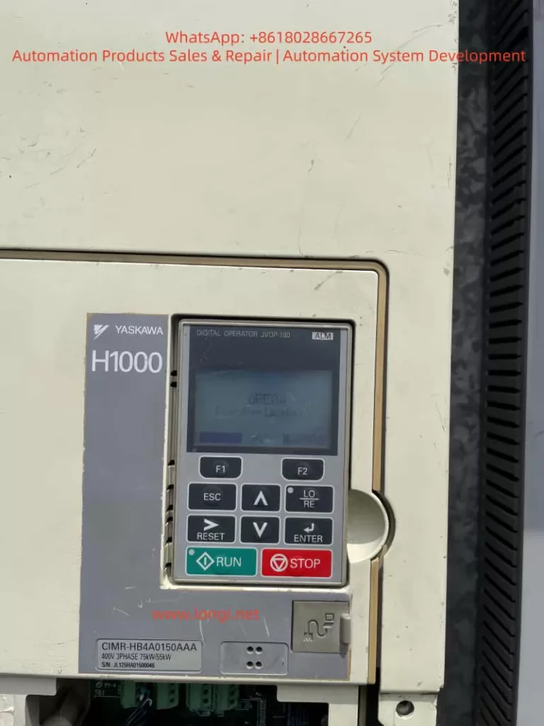
- Tool Preparation: Phillips screwdriver, anti-static wrist strap, operation panel (JVOP-180, the digital operator in the picture).
Step 2: Enter Parameter Mode
- Press the ESC key to exit the fault display and return to standby (screen shows “STOP”).
- Long-press the MODE key (for ~3 seconds) until the screen displays “Pr. 0” (indicating entry into parameter mode).
Step 3: Locate the “Motherboard Replacement Confirmation” Function Code
The “motherboard replacement confirmation” function code for the Yaskawa H1000 series is usually Pr. 777 (some versions may use Pr. 778 or others—refer to the manual). The parameter values mean:
- 0: Motherboard replacement not confirmed (default, triggers OPE04 fault).
- 1: Motherboard replacement confirmed (initialization completed, fault eliminated).
Step 4: Modify the Parameter Value
- Use the ↑/↓ keys to change Pr. 777 from “0” to “1”.
- Press the ENTER key to confirm the modification (screen shows “Pr. 777=1”).
Step 5: Restart the Inverter
- Cut off the inverter power and wait 1 minute before re-energizing.
- After power-on, if the screen shows “RUN” or “STOP” (no fault code), the initialization is successful, and the OPE04 fault is eliminated.
5. Troubleshooting OPE04 Fault Without Motherboard Replacement: Hardware Contact and System False Alarms
If the OPE04 fault is triggered without proactive motherboard replacement, it is usually caused by hardware contact failures or system false alarms. Follow these steps to troubleshoot:

5.1 Check Hardware Contact Failures
Step 1: Disconnect Power
- Cut off the inverter’s input power and wait for the DC bus capacitor to discharge (use a multimeter to measure the DC bus voltage to ensure it is below 36V).
Step 2: Open the Inverter Casing
- Use a Phillips screwdriver to remove the casing fixing screws and open the cover (avoid damaging internal components).
Step 3: Inspect Motherboard Connections
- Locate the connector between the control motherboard and the base plate (usually on the edge of the motherboard, marked as “CN1” or “CN2”).
- Gently pull out the connector and check if the pins are oxidized (e.g., blackened pin surface), bent (e.g., skewed pins), or dirty (e.g., dust, oil).
- Wipe the pins and socket with anhydrous alcohol (do not use gasoline or acetone to avoid corrosion). After the alcohol evaporates, reinsert the connector (ensure full insertion, no skewness).
Step 4: Reinstall the Casing and Power On
- Reinstall the casing and tighten the fixing screws.
- After power-on, if the OPE04 fault disappears, the problem is solved; if not, proceed to the next step.
5.2 Restore Factory Settings (Caution!)
If the hardware contact is good but the fault persists, it may be a system parameter conflict causing a false alarm. You can try restoring factory settings (note: this operation clears all user parameters—back up first):
Step 1: Enter Parameter Mode
- Press the ESC key to exit the fault display and long-press the MODE key to enter parameter mode.
Step 2: Locate the “Restore Factory Parameters” Function Code
The “restore factory parameters” function code for the Yaskawa H1000 series is usually Pr. 778. The parameter values mean:
- 0: Keep current parameters (default).
- 1: Restore factory parameters (clears all user parameters).
Step 3: Restore Factory Parameters
- Use the ↑/↓ keys to change Pr. 778 to “1”.
- Press ENTER to confirm— the screen will show “Pr. 778=1” (indicating restoration in progress).
- Wait ~10 seconds until the screen shows “END” (restoration completed).
Step 4: Reconfigure Parameters and Verify
- Reconfigure user parameters based on actual applications (e.g., Pr. 3 = motor rated voltage, Pr. 4 = motor rated current).
- Restart the inverter—if the OPE04 fault disappears, the problem is solved.
6. Preventive Maintenance Strategies for OPE04 Fault
To avoid recurrent OPE04 faults, establish a standardized maintenance process:
6.1 Regular Hardware Inspection
- Conduct a visual inspection of the inverter quarterly, focusing on whether the motherboard connector is loose or oxidized (oxidized pins will blacken).
- Perform internal cleaning annually—blow dust off the motherboard surface with compressed air (avoid dust accumulation causing poor contact).
6.2 Standardize Motherboard Replacement Operations
- When replacing the motherboard, power off and wear an anti-static wrist strap.
- Before installing the new motherboard, check that its model matches the original (e.g., the H1000 motherboard model is “CIMR-HB4A0150AAA”—confirm the new motherboard’s model).
- After replacement, initialize (i.e., set Pr. 777 = 1) to avoid triggering the OPE04 fault.
6.3 Backup Parameters
- Back up the inverter’s user parameters regularly (e.g., quarterly) via the operation panel (select “Parameter Backup” function) or Yaskawa DriveWizard software (connect via RS-485 communication interface).
- Store backup files on non-volatile media (e.g., USB drive, cloud storage) to avoid parameter loss due to hard disk failure.
7. Practical Case Studies
Case 1: OPE04 Fault After Proactive Motherboard Replacement
Fault Phenomenon: An H1000 inverter (model CIMR-HB4A0150AAA) in a food factory triggered the OPE04 fault after replacing the motherboard due to a capacitor breakdown. The inverter could not start.
Troubleshooting Process:
- Confirmed the user had replaced the motherboard and not performed initialization.
- Guided the user to enter parameter mode and set Pr. 777 = 1.
- After restart, the fault disappeared, and the inverter returned to normal operation.
Conclusion: After proactive motherboard replacement, initialization is mandatory—otherwise, the OPE04 fault will be triggered.
Case 2: OPE04 Fault Without Motherboard Replacement
Fault Phenomenon: An H1000 inverter (model CIMR-HB4A0150AAA) in a water plant suddenly displayed the OPE04 fault. The user had not replaced the motherboard.
Troubleshooting Process:
- Disconnected power, opened the casing, and found oxidation on the CN1 connector pins.
- Wiped the pins and socket with anhydrous alcohol and reinserted the connector.
- After power-on, the fault disappeared.
Conclusion: Connector oxidation caused poor contact, and the system falsely detected a “motherboard replacement.” The fault was resolved after cleaning.
8. Conclusion
The OPE04 fault of the Yaskawa H1000 inverter is essentially a system requirement for confirming motherboard changes—whether proactive replacement or passive false alarm, it requires resolution via hardware inspection or software initialization. Technicians must master the following core points:
- Fault Definition: OPE04 is a “motherboard replacement detection fault” that requires confirming the motherboard replacement status.
- Troubleshooting Process:
- Proactive motherboard replacement: Set Pr. 777 = 1 to complete initialization.
- No motherboard replacement: Check hardware contact and restore factory settings if necessary.
- Preventive Measures: Standardize replacement operations, inspect connections regularly, and back up parameters.
Through the analysis in this article, I believe technicians can quickly locate the cause of the OPE04 fault and take correct measures to ensure the inverter operates stably. In practical applications, if complex issues arise (e.g., the fault persists after initialization), contact Yaskawa technical support or a professional maintenance personnel to avoid greater losses due to misoperation.
Appendix: Common Function Codes for Yaskawa H1000 Series Inverters
| Function Code | Name | Default Value | Meaning |
|---|---|---|---|
| Pr. 777 | Motherboard Replacement Confirmation | 0 | 0 = Not Confirmed; 1 = Confirmed |
| Pr. 778 | Restore Factory Parameters | 0 | 0 = Keep; 1 = Restore Factory Parameters |
| Pr. 0 | Control Mode Selection | 0 | 0 = V/F Control; 1 = Vector Control |
| Pr. 1 | Rated Frequency | 60Hz | Rated frequency of the motor |
| Pr. 3 | Rated Voltage | 380V | Rated voltage of the motor |
(Note: Function codes may vary by firmware version—refer to the actual manual.)