Posted on Leave a comment

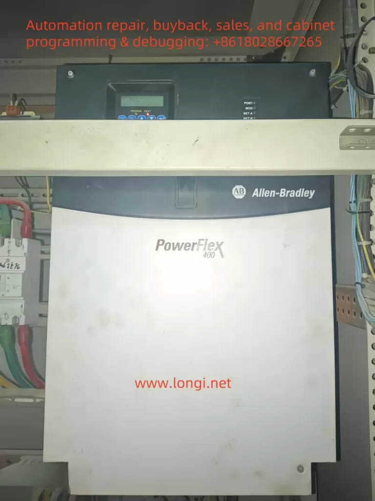
Analysis and Solution of F 032 Fault in Rockwell PowerFlex 400 Series Inverter


The Rockwell (Allen-Bradley) PowerFlex 400 series inverter is a widely used, high-performance device in industrial automation, valued for its stability and reliability. However, during prolonged operation, it may encounter faults, one of which is the F 032 fault, known as Fan Feedback Loss. This article analyzes this fault in detail—its meaning, causes, on-site troubleshooting steps, and repair methods—offering clear guidance for field engineers to restore equipment operation efficiently.


What the F 032 Fault Means and Why It Happens

Meaning of the Fault

The F 032 fault code indicates Fan Feedback Loss, a common issue in Frame E and F models (higher power units) of the PowerFlex 400 series. These models feature a cooling fan feedback monitoring system. When the inverter cannot detect the fan’s normal operation, it triggers this fault and shuts down to prevent overheating damage.
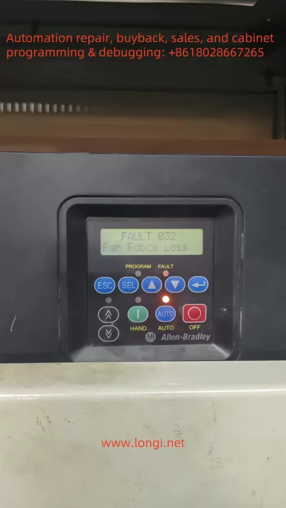
f032

How It Occurs

The inverter generates significant heat during power conversion, and the cooling fan is essential to keep internal components (like IGBT modules and capacitors) at safe temperatures. In Frame E and F models, the fan sends a feedback signal to the inverter’s control system to confirm it’s working. If this signal is lost—due to fan failure, wiring issues, or control circuit problems—the F 032 fault is activated.

Possible Causes:

  • Fan Mechanical Failure: Blocked blades, damaged motor, or seized bearings.
  • Power/Circuit Problems: Open or short circuits, or loose power supply connections.
  • Feedback Signal Issues: Disconnected, broken, or faulty signal lines or control board circuits.
  • Environmental Factors: Excessive heat or dust affecting fan performance.

Why It Matters

The F 032 fault is a self-protection mechanism. Without proper cooling, sensitive components could overheat, leading to equipment failure. By stopping operation, the inverter prevents damage, prioritizing long-term reliability over temporary production continuity.


On-Site Troubleshooting Steps

When an F 032 fault appears, follow these steps to diagnose and fix it quickly, minimizing downtime:

  1. Check Fan Operation
  • Action: Power off the inverter, open the panel, and check if the fan spins.
  • Steps: Remove dust or debris from blades; manually spin the fan to detect jams or resistance.
  • Goal: Rule out mechanical issues.
  1. Inspect Power and Control Circuits
  • Action: Examine the fan’s power and signal line connections.
  • Steps: Use a multimeter to verify voltage at the fan’s power terminal; check for circuit breaks or shorts.
  • Goal: Ensure power delivery isn’t the issue.
  1. Verify Feedback Signal Lines
  • Action: Check the connection between the fan’s feedback line and the control board.
  • Steps: Confirm the line isn’t loose or broken; test continuity with a multimeter if possible.
  • Goal: Fix signal transmission problems.
  1. Reset and Test
  • Action: Reset the fault via the panel’s “FAULT RESET” button or programming mode.
  • Steps: Restart the inverter and monitor if the fault recurs; continue operation if cleared.
  • Goal: Confirm if it was a temporary glitch.
  1. Review Parameter Settings
  • Action: Access programming mode to check fan monitoring parameters (e.g., P040).
  • Steps: Verify the function is enabled and settings are correct.
  • Goal: Eliminate false alarms from misconfiguration.
  1. Assess Environmental Conditions
  • Action: Evaluate the inverter’s surroundings.
  • Steps: Clean the heat sink; ensure ambient temperature is within 0-50°C.
  • Goal: Address environmental triggers.

Most F 032 faults can be resolved with these steps. If the issue persists, deeper repairs are needed.


Repair Methods When On-Site Fixes Fail

If troubleshooting doesn’t work, the problem may involve hardware damage. Here’s how to proceed:

  1. Disassemble the Inverter
  • Action: Power off, discharge residual voltage, and remove the casing.
  • Tips: Follow safety protocols; note disassembly steps for reassembly.
  • Tools: Screwdriver, multimeter.
  1. Examine Fan and Circuits
  • Action: Inspect the fan, power lines, control lines, and feedback lines.
  • Steps: Test power supply voltage; look for burns or breaks in circuits.
  • Fix: Repair or replace damaged parts; test the fan next if power is fine.
  1. Test the Fan Independently
  • Action: Connect the fan to a separate power source.
  • Steps: Check if it spins; replace it if it doesn’t (use a matching model).
  • Tips: Ensure compatibility with the original fan.
  1. Check the Control Board
  • Action: Inspect the main control board or fan control circuit.
  • Steps:
    • Look for burned components or loose solder joints.
    • Test feedback signal input with a multimeter.
    • Identify issues like damaged chips or connectors.
  • Fix: Re-solder joints; replace faulty components; consider board replacement if damage is severe.
  1. Reassemble and Verify
  • Action: Reassemble, power on, and test.
  • Steps: Confirm fan operation and fault clearance; monitor cooling performance.
  • Goal: Ensure the repair worked.

powerflex 400

Preventing Future F 032 Faults

To minimize recurrence:

  • Routine Cleaning: Clear dust from the inverter and fan every three months.
  • Wiring Checks: Regularly inspect power and signal line connections.
  • Ventilation: Keep the installation area well-ventilated and within temperature limits.

Conclusion

The F 032 fault in the PowerFlex 400 series inverter is a vital alert tied to fan failure, designed to prevent overheating damage. By understanding its causes and following structured on-site troubleshooting, engineers can often resolve it quickly. For persistent issues, detailed repairs targeting the fan or control board are effective. Combined with preventive maintenance, these steps ensure equipment reliability and support uninterrupted industrial operations.

Posted on Leave a comment

Principles and Troubleshooting Guide for the FANUC αi Series Drive AL-81 Alarm

In modern industrial automation, FANUC CNC systems are widely used in CNC machine tools, robots, and a variety of automated equipment. Renowned for high reliability, precision, and scalability, FANUC products have gained the trust of manufacturing enterprises worldwide. Among the various alarms that can arise when using FANUC αi series drives (including servo amplifiers and spindle amplifiers), one of the most common and sometimes puzzling is the “AL-81” alarm. This article will focus on the meaning of the AL-81 alarm, the scenarios under which it appears, troubleshooting methods, and frequently asked questions. The aim is to help readers quickly and effectively carry out fault diagnosis and resolution.


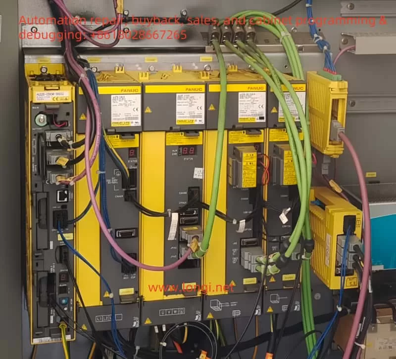
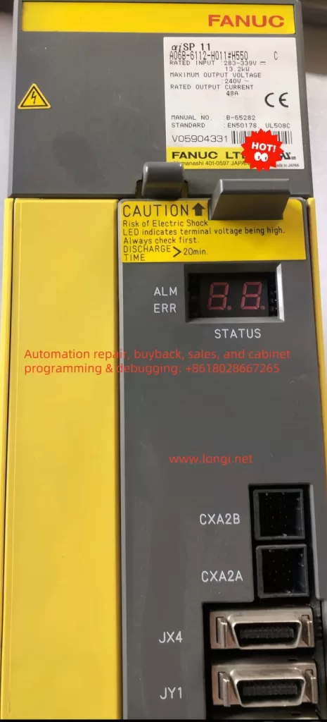
Physical image of α i SP drive

I. The Meaning of the AL-81 Alarm

On FANUC αi SP (spindle drives) or αi SV (servo drives), the “81” alarm typically indicates that the drive has not completed its internal parameter initialization. In other words, the drive cannot properly recognize the axis number assigned to it by the CNC system, or the amplifier parameters necessary for operation have not yet been written to it. Under normal circumstances, a FANUC αi series drive will exchange data with the CNC system, including amplifier identification, servo/spindle parameters, and communication settings. If something goes wrong—such as a newly installed drive without parameter input, or an existing drive whose internal data has been cleared—the AL-81 alarm will remain active.

It is worth noting that this alarm typically appears just after the drive is powered on or reset, as the system checks for proper drive identification and parameter download. If the CNC controller cannot “recognize” the drive and transfer the correct parameters, the drive will report the AL-81 alarm and enter an inoperative alarm state. At this point, the user will see “AL-81” or a similar two-digit code on the drive’s panel or display.


II. Common Scenarios Leading to the Alarm

  1. Replacing a Drive without Completing Parameter Initialization
    When an older αi series drive fails and is replaced with a new one, but no parameter-writing procedure is performed via the CNC’s maintenance mode, an AL-81 alarm will appear. A new drive generally has no specific axis parameters programmed from the factory and requires the CNC to download the necessary configuration data.
  2. Parameter Loss after Main Board or System Component Initialization
    During maintenance or replacement of the CNC main board, or after restoring system data from a backup, certain critical files or parameters may fail to synchronize correctly with the drive. In particular, in multi-axis machine or multi-drive systems, the fiber-optic (FSSB) communication setup is crucial. If the sequence or configuration is not aligned, it may trigger the AL-81 alarm because the drive lacks the required internal identification parameters.
  3. Incorrect Fiber-Optic Connections or Axis Number Assignments
    In machines with multiple axes and multiple drives, the servo and spindle amplifiers typically communicate with the CNC via fiber-optic cables (FSSB channels). If the user changes the fiber-optic order or fails to match the correct axis assignments, the drive will not establish the proper correlation with the CNC upon power-up, triggering the AL-81 alarm. The system detects a mismatch between the drive’s internal ID and the CNC parameters, causing the alarm.
  4. Drive Memory Failure or Hardware Incompatibility
    Although less common, the drive’s internal memory may become damaged or its hardware may degrade after many years of operation, resulting in an inability to store parameters. Additionally, if the replacement drive model is significantly different from the original—due to a different power rating, for instance—simple parameter writing may not remedy the hardware discrepancy, leading to a persistent AL-81 or other alarms.

III. Troubleshooting and Resolution

  1. Perform Drive Initialization (AIF Parameter Writing)
    • Enter the CNC’s maintenance mode (often called Maintenance Mode or a similar advanced-privilege screen) and locate the “Amplifier/Servo Initialization” or “AIF” option.
    • Allow the system to automatically detect the new drive and download the required parameters into the amplifier. During this process, the CNC will scan for the drive, prompt to overwrite or write parameters, and generally require following machine-specific or manufacturer-provided instructions.
    • After parameter writing is complete, shut down and then power the system back on. In most cases, the AL-81 alarm will clear automatically.
  2. Check Fiber-Optic (FSSB) Connections and Axis Configuration
    • In multi-drive setups, the fiber-optic cables’ order and each drive’s designated axis numbers must match the CNC settings. For example, the spindle drive might be connected on the first channel, with servo drives following in subsequent channels.
    • If you have disconnected the fiber-optic cables, carefully confirm their original sequence. Ensure each cable is reconnected to the correct amplifier port and that the CNC parameters reflect the correct axis.
    • Some machine builders label drives or cables clearly, indicating which cable goes where, thus helping to avoid confusion when reattaching connections.
  3. Confirm Drive Model and Power Compatibility
    • When replacing a drive, make sure you select a model that is compatible with the original, matching in power, rated current, and interface specifications. If there is a large difference between the old and new drives, parameter writing alone may not be sufficient to achieve normal operation.
    • If you are uncertain about compatibility, refer to the original manufacturer’s technical manuals, data from the machine tool builder, or consult a professional engineer.
  4. Reset or Inspect the Drive Hardware
    • If you have completed the initialization process and verified your connections, but the AL-81 alarm persists, you could try a more thorough reset of the drive.
    • In FANUC systems, there are sometimes special methods or software tools required for deeper clearing or parameter-writing procedures. Refer to machine documentation or contact technical support for details.
    • If no improvement is observed, you may suspect a genuine hardware fault in the drive itself and consider further inspection, factory repair, or replacement.

IV. Frequently Asked Questions

  1. Why do I sometimes see numbers like “51” or “B1” on the panel instead of “81”?
    • Under certain lighting angles, display types, or different drive versions, digits like “8” and “B,” or “1” and “I,” can be visually confusing. Checking the official drive manual helps confirm the true alarm code is “81.”
  2. Is it a fault if the power supply unit (αiPS) displays “4” or another number?
    • Many FANUC power supply units display internal status codes during normal operation, rather than error codes. Only when you see an “E” code on the power unit or abnormal indicator lights should you suspect a fault in the power supply.
    • Consequently, if the αiPS only shows “4” (and not “E-xx” or similar), it generally indicates normal operation.
  3. If it is an absolute encoder issue, why is the alarm not AL-81?
    • When an absolute encoder loses power or the battery voltage drops, you usually see alarms such as “bL,” “bF,” or other encoder-related messages at the CNC level. These are unrelated to the drive initialization issue represented by AL-81.
  4. Why does the alarm remain even after initialization?
    • It’s possible that something went wrong during the initialization or parameter writing process—maybe the system failed to properly recognize the drive or the user skipped a critical step.
    • Another possibility is that the physical connections (e.g., fiber-optic cables) remain incorrect: reversed connections, poor contact, or the wrong channel sequence.
    • If these causes are ruled out, the drive hardware itself may be faulty, requiring more advanced inspection or repair.

On site working diagram of α i

V. Conclusion

When an AL-81 alarm appears on a FANUC αi series drive in a CNC machine tool or automated production line, it does not necessarily mean the hardware is broken. More often, it is a common fault triggered by incomplete initialization or parameter mismatch. By performing parameter writing on the drive, checking fiber-optic connections, and confirming model compatibility, most AL-81 alarms can be resolved within a short time. If all settings have been validated and the alarm still will not clear, it is advisable to investigate possible hardware failure in the drive and, if necessary, consult professional technical support or send the drive for factory repair.

When using a FANUC CNC system, it is crucial to maintain complete machine documentation and service records, as well as to perform regular backups and checks. Doing so ensures that, when any fault arises—whether AL-81 or otherwise—existing information can be used to pinpoint the cause quickly and to restore production following the proper guidelines, saving both time and resources for the enterprise.

Posted on Leave a comment

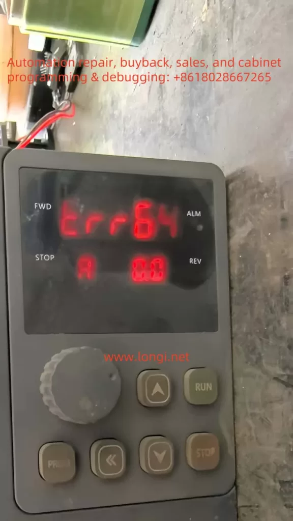
M900 Inverter err64 Fault: Meaning, Root Cause Analysis, and Solutions

M900 Inverter err64 Fault: Meaning, Root Cause Analysis, and Solutions

(This article discusses the background of the “err64” fault in M900 series inverters, its potential causes, deeper hardware-level analyses, and practical troubleshooting steps. The goal is to help electrical maintenance personnel target the problem more effectively. This text, of over 1,000 words in its Chinese original, covers both theoretical and hands-on repair perspectives.)


I. Background and Meaning of err64

In typical inverter applications, the most common faults involve overcurrent, overvoltage, undervoltage, overload, and cooling fan issues. However, in certain cases—especially after repairs or the replacement of internal components—M900 inverters may display a “err64” fault code. According to the manufacturer’s technical support, “err64” is not listed in the usual user manual but indicates a communication failure between the main control board and the driver board.

In other words, the inverter’s primary control circuitry (often referred to as the “master” or “main” board) and its power drive unit (“driver” board) cannot exchange data, causing the control system to fail to operate properly and thus triggering a fault protection.

To understand this issue, one must note that an M900 inverter typically consists of at least two major sections: a control board (hosting the microcontroller or DSP as the core of the logic) and a driver board (housing the power modules, IGBTs, or related gate driver circuitry). These boards communicate via a dedicated interface or set of pins. Sometimes, there may also be a small power supply board or other auxiliary boards, but the communication link between the main board and the driver board is central to the entire system. Once that link is broken or corrupted, the inverter will report a “board-to-board communication error” such as “err64” and shut down to protect itself.


II. Common Causes of err64

  1. Loose or Faulty Ribbon Cable/Connector
    During maintenance or reassembly, a ribbon cable or connector might not have been fully seated, or its metal pins could be bent, oxidized, or otherwise damaged. This often leads to poor signal transmission or no transmission at all, and is one of the most frequent root causes for communication errors.
  2. Damaged Hardware Chips
    • Burned-out Transceiver/Bus Chip: The communication between the control and driver boards usually involves specialized transceiver components (e.g., RS485 driver chips, optical isolators, or TTL level transceivers). If subjected to excessive heat, current surge, or electrostatic discharge, these chips can fail and interrupt the data link.
    • Main CPU or Driver DSP Failure: Though less common, serious power surges, extended over-temperature conditions, or short-circuit mishandling can damage the main controller or DSP on either board. When that happens, the inverter can no longer exchange valid data, triggering the err64 alarm.
  3. Auxiliary Power Supply Issues
    The main board and driver board typically rely on a regulated power supply—often +5V or +3.3V—to operate their digital circuits. If this low-voltage supply is weak or unstable, or if a regulator (LDO, DC-DC converter) on either board is failing, then even intact chips may produce garbled signals and fail to establish proper communication.
  4. Secondary Damage During Fan or Relay Replacement
    Many reported err64 errors occur soon after a user replaces a fan or relay. This suggests that the process may introduce secondary problems:
    • An incompatible relay or altered circuit parameters causing abnormal power conditions;
    • Accidental short-circuits or soldering damage during the repair;
    • The inverter may already be partially degraded from prior overheating, so additional stress completes the failure pathway.

III. Root Cause Analysis and Troubleshooting

At its core, “err64” represents an internal communication failure. This communication is usually a low-level or custom protocol rather than a typical external fieldbus (like Modbus). As a result, the inverter’s diagnostic does not offer many granular details. Because the issue can lie in various hardware points, it is best to follow a structured approach:

  1. Physical Inspection and Connector Checks
    • First, turn off power and wait long enough for internal capacitors to discharge (generally at least 10 minutes).
    • Open the inverter casing to inspect all connectors, paying particular attention to the flat cables and sockets between the main board and driver board. Look for signs of looseness, oxidation, broken plastic housings, or bent pins.
    • Clean off any dust or grime with an appropriate solution such as isopropyl alcohol. Dry thoroughly, re-seat the connectors firmly, then restart and see if the error persists.
    • This preliminary step is simple but can resolve many “false” faults that arise after vibrations or reassembly.
  2. Supply Rails and Signal Tests
    • Use a multimeter to check the low-voltage rails (+5V, +3.3V, etc.) on both the control and driver boards. Confirm stable, correct output levels.
    • If available, use an oscilloscope to observe the communication pins (TX, RX, or RS485 differential signals) for pulses or signals. If the line is held at a steady voltage with no pulses, it indicates that the transmitter is not functioning (which could mean the transceiver or even the CPU is compromised).
    • If the signal is noisy or the amplitude is too low, consider the possibility of defective coupling resistors, capacitors, or the transceiver chip itself.
  3. Suspecting Transceiver or MCU Failure: The Swap/Replacement Method
    • After verifying connectors, supply rails, and passive components, you may try replacing the communication transceiver chip with one of the same model if you suspect it is burned out.
    • If replacing the transceiver chip does not help, the fault may lie in the main CPU, driver DSP, or other major components on the board. Diagnosing or replacing these can require specialized tools and is best handled by trained professionals.
  4. Reset to Factory Defaults or Firmware Update
    • Occasionally, firmware or software anomalies can also trigger internal communication timeouts.
    • Attempt a factory reset (restoring default parameters) and then power up again to see if the fault clears. If the manufacturer provides a firmware update procedure, you can try upgrading the system firmware. However, if the hardware is physically damaged, these software-level attempts typically will not resolve an err64 alarm.

IV. Precautions and Preventive Measures

  1. Prompt Cooling System Maintenance
    If the M900 inverter’s cooling fan stops working or its venting is blocked, the internal boards can operate at high temperatures, accelerating aging. Quick repair or replacement of fans can prevent serious damage that leads to communication issues.
  2. Standardized Repair Operations
    • Always allow adequate discharge time after powering off the inverter to avoid electric shock or component damage.
    • When replacing a relay or other parts, match the specifications (coil voltage, contact ratings, etc.) exactly.
    • Proper soldering tools and techniques are crucial—poorly done solder joints or bridging can damage sensitive PCB traces and components.
  3. Cleanliness and Protective Practices
    • In dusty or humid environments, regularly open the inverter casing for an internal check and cleaning.
    • If connectors or components show corrosion or rust, replace or clean them promptly.
    • Perform these repairs or inspections in as clean an environment as possible, avoiding metal particles, oil, or fine dust contamination on open circuit boards.
  4. Fault Log and Data Recording
    • If the inverter can store internal logs or provide real-time data, document those details as soon as a fault appears.
    • Observing the inverter’s normal operating waveforms versus the state just before a failure can guide you to the precise area of malfunction.

Conclusion

In summary, an M900 inverter reporting “err64” indicates a lost or compromised communication link between its main control board and driver board. This can stem from something as simple as a partially inserted ribbon cable or can be as severe as a failed bus transceiver chip or main CPU.

The recommended troubleshooting approach is systematic:

  1. Inspect and re-seat cables and connectors;
  2. Verify supply voltages and signals;
  3. Replace suspect transceiver and check associated passive parts;
  4. Finally, if those attempts fail, look toward the main CPU, DSP, or more advanced board-level repairs.

Meanwhile, ensuring proper cooling, following proper service procedures, and regularly cleaning the inverter’s internals will significantly lower the likelihood of such communication failures. If all methods are exhausted, contacting a professional repair center or the manufacturer is advisable for advanced diagnostics. By fully understanding the root cause and progression of “err64” faults, you can remedy them swiftly and maintain the M900 inverter’s reliability for critical industrial processes.

Posted on Leave a comment

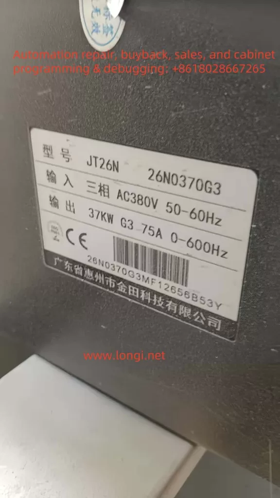
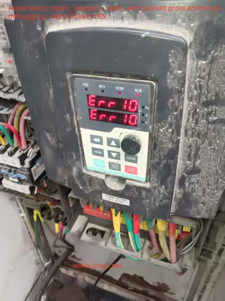
JTE Inverter JT26N Usage Guide and ERR10 Fault Resolution

The JTE Inverter JT26N series is a high-performance general-purpose inverter widely used in various industrial control scenarios. This article provides a detailed introduction to the usage of this inverter, including panel startup and speed adjustment settings, external terminal forward/reverse and external potentiometer speed adjustment settings, parameter copying and initialization methods, as well as the meaning and resolution of the ERR10 fault.

JT26N physical image

I. Basic Settings for the JTE Inverter JT26N

1. Panel Startup and Speed Adjustment Settings

The panel startup and speed adjustment settings for the JTE Inverter JT26N are relatively straightforward. Users can complete basic startup and speed adjustment operations through the buttons and display on the control panel. Here are the specific steps:

  1. Startup Settings:
  • Press the “PRGM” key to enter programming mode.
  • Use the “Δ” and “∇” keys to select the function code F0-02, and confirm that the command source is set to the control panel command channel (value 0).
  • Press the “ENTER” key to confirm the setting.
  1. Speed Adjustment Settings:
  • In programming mode, select the function code F0-03 and set the main frequency source X to panel potentiometer speed adjustment (value 1).
  • Adjust the frequency by rotating the potentiometer on the panel to achieve speed control.

2. External Terminal Forward/Reverse and External Potentiometer Speed Adjustment Settings

The JTE Inverter JT26N supports forward/reverse control and external potentiometer speed adjustment functions through external terminals. Here are the specific wiring and setup methods:

  1. Forward/Reverse Control:
  • Wiring: Connect the external control signal to the digital input terminals of the inverter (such as MI1, MI2, etc.).
  • Settings: In programming mode, select the function code F0-09 and set the running direction to forward (value 0) or reverse (value 1).
  1. External Potentiometer Speed Adjustment:
  • Wiring: Connect the signal line of the external potentiometer to the analog input terminals of the inverter (such as AI1, AI2, etc.).
  • Settings: In programming mode, select the function code F0-03 and set the main frequency source X to external potentiometer speed adjustment (value 2, 3, or 4, depending on the specific terminal).

II. Parameter Copying and Initialization

1. Parameter Copying

The JTE Inverter JT26N supports parameter copying, allowing users to copy parameters from one inverter to another. Here are the specific steps:

  1. Prepare a blank storage card or USB drive and insert it into the parameter copying interface of the inverter.
  2. Press the “PRGM” key to enter programming mode and select the parameter copying function.
  3. Follow the prompts to copy the parameters to the storage card or USB drive.
  4. Insert the storage card or USB drive into another inverter and follow the prompts to copy the parameters to the new inverter.

2. Parameter Initialization

In some cases, users may need to initialize the inverter parameters. Here are the specific steps:

  1. Press the “PRGM” key to enter programming mode.
  2. Select the function code F0-27 and set the parameter initialization option to fully initialize parameters (value 03).
  3. Press the “ENTER” key to confirm, and the inverter will reset to factory settings.

III. Meaning and Resolution of the ERR10 Fault

1. Meaning of the ERR10 Fault

The ERR10 fault is a common fault code for the JTE Inverter JT26N, indicating an overload condition. An overload occurs when the output current of the inverter exceeds its rated current, which may be caused by the following reasons:

  1. The load is too large, exceeding the rated capacity of the inverter.
  2. There is a mechanical fault in the motor or other load equipment, causing abnormal current increases.
  3. The parameter settings of the inverter are incorrect, leading to overload protection activation.

2. Handling the ERR10 Fault

When the ERR10 fault occurs on-site, users should follow these steps to address it:

  1. Check the Load: Ensure that the load is within the rated capacity range of the inverter, reducing the load if necessary.
  2. Inspect the Motor and Equipment: Check the motor and other load equipment for mechanical faults, such as jamming or excessive resistance.
  3. Verify Parameter Settings: Ensure that the inverter’s parameter settings are correct, especially those related to the load.
  4. Restart the Inverter: After confirming that the load and equipment are normal, restart the inverter and observe if the ERR10 fault still occurs.

3. Repair Methods for the ERR10 Fault

When repairing the internal circuit board of the inverter after an ERR10 fault, users should follow these steps:

  1. Inspect Under Power-Off Conditions: Open the inverter’s casing in a power-off state and inspect the internal circuit board for any visible damage or burnout.
  2. Clean the Circuit Board: Use a clean cloth or cotton swab dipped in isopropyl alcohol to gently wipe the surface of the circuit board, removing dust and dirt.
  3. Replace Damaged Components: If any damaged or burned components are found on the circuit board, replace them with new components of the same model.
  4. Reassemble: After ensuring that the circuit board has no visible faults, reassemble the inverter and perform a functional test.
ERR10

IV. Conclusion

The JTE Inverter JT26N is a powerful and easy-to-operate inverter suitable for various industrial control scenarios. By correctly setting up panel startup and speed adjustment, external terminal forward/reverse, and external potentiometer speed adjustment, users can easily achieve basic control functions of the inverter. Additionally, the inverter supports parameter copying and initialization functions, making it convenient for users to manage parameters. In the event of an ERR10 fault, users should promptly check the load and equipment and follow the correct procedures for handling and repair to ensure the normal operation of the inverter.

Posted on Leave a comment

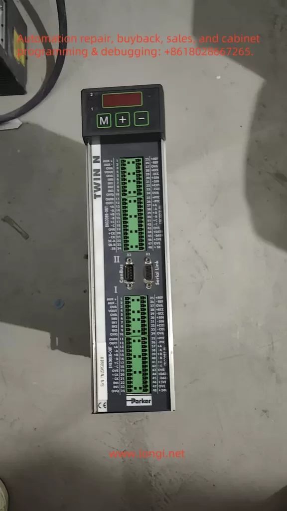
User Guide for Parker Servo System TWIN5NS(TWIN-N/SPD-N) Series

The Parker servo system TWIN-N/SPD-N series is a high-performance servo drive system widely used in industrial automation, robotics, and precision control applications. This guide provides detailed instructions on how to perform jog testing, position mode control, electronic cam functionality, and troubleshooting for this system.

TWIN5NS physical picture

1. Jog Testing

Jog testing is a crucial step in the calibration and verification of servo systems. Here’s a detailed guide on how to perform jog testing:

Wiring Steps:

  • Power Connection: Connect the three-phase power supply lines L1, L2, and L3 to the drive’s terminals 1, 2, and 3, respectively. For single-phase or DC power supply, refer to the user manual for the appropriate wiring diagram.
  • Motor Connection: Connect the motor’s U, V, and W phases to the drive’s terminals 5, 6, and 7 (Motor I). For dual-axis drives (TWIN-N), connect the second motor’s U, V, and W phases to terminals 9, 10, and 11 (Motor II).
  • Encoder Connection (if used): For incremental encoders, connect the A+, A-, B+, and B- signal lines to terminals 13, 14, 15, and 16, respectively. For sine/cosine encoders, connect the Sin+, Sin-, Cos+, and Cos- signal lines to terminals 6, 7, 8, and 9, respectively.
  • Control Signal Connection: Connect the 24V control power supply to terminals 24 and 48. Connect the analog reference input to terminals 1 and 2 (Rif. AUX + and Rif. AUX -). Connect the JOG operation buttons to digital input terminals (e.g., IN0, IN1) for start, stop, and direction control.

Parameter Settings:

  • Initialize Parameters: After powering on, set the drive to default parameters using the keypad. Set b99.7 and b99.13 to 0, issue command b99.12, and save the settings (b99.14 and b99.15).
  • Set Motor Parameters: Input motor parameters such as pole count (Pr29), rated speed (Pr32), rated current (Pr33), encoder pole count (Pr34), motor impedance (Pr46), and inductance (Pr47).
  • Set Feedback Type: Configure feedback parameters based on the encoder type (e.g., b42.9, b42.8, b42.7, b42.6).
  • Adjust Speed Loop Parameters: Set the integral gain (Pr16) and damping (Pr17) of the speed loop, adjusting based on system response.
  • Set Acceleration/Deceleration Time: Configure acceleration and deceleration times (Pr8, Pr9, Pr10, Pr11).
  • Set Limiting Parameters: Set overspeed limit (Pr13), high-speed limit (Pr14), low-speed limit (Pr15), and peak current (Pr19).

Jog Operation Procedure:

  1. After powering on, start the JOG operation by pressing the corresponding buttons. One button can start the motor in the forward direction, and another can start it in reverse.
  2. Releasing the button should stop the motor immediately or according to the set deceleration.

Open-Loop Mode Testing:

In open-loop mode (without an encoder), the drive operates the motor using V/F control by varying the frequency of the input voltage. Set the motor type to asynchronous (Pr217 = 1) and input related parameters such as base speed (Pr218), slip (Pr219), and magnetizing current (Pr220). In this mode, the drive estimates the motor’s speed and position by detecting the back EMF.

2. Position Mode Forward and Reverse Control

Position mode control is commonly used in servo systems to precisely control the motor’s position. Here’s how to implement forward and reverse control in position mode:

Wiring Steps:

  • In addition to the power and motor connections, connect a position feedback device (e.g., an encoder) to the drive’s corresponding terminals.

Parameter Settings:

  • Set Position Mode: Select the position mode in the operation settings (e.g., Pr31 = 13 or 14).
  • Set Position Parameters: Configure target position (e.g., Pr62:63), speed (Pr8, Pr9), and acceleration (Pr10, Pr11).
  • Enable Position Control: Ensure the position feedback device is correctly connected and calibrated.

Forward and Reverse Control:

Control the motor’s forward and reverse rotation by setting the target position to positive or negative values. For example, a positive target position will rotate the motor forward, while a negative value will rotate it in reverse.

3. Electronic Cam Functionality

The electronic cam function is an advanced feature of servo systems used for complex motion control. Here’s how to implement it:

Implementation Steps:

  • Set Electronic Cam Parameters: Select the electronic cam mode in the operation settings (e.g., Pr31 = 14). Configure the cam table parameters, such as position, speed, and acceleration.
  • Configure Cam Table: Set up the data points in the cam table according to the motion requirements.

Using CAN Protocol:

  • CAN Wiring: Connect the CAN communication lines to the drive’s CAN interface terminals.
  • Set CAN Parameters: Configure the CAN communication speed (e.g., Pr48) and CANopen address (e.g., Pr49).
  • Configure CAN Communication: Set up the data frames and control words for CAN communication according to the user manual.
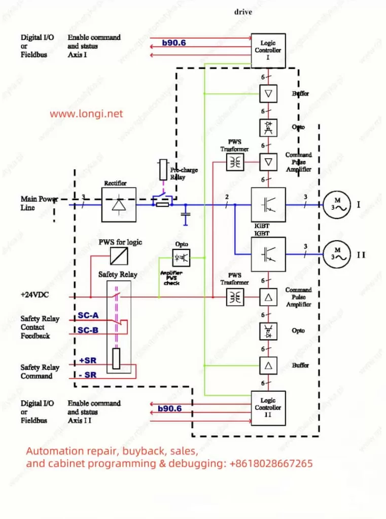
TWIN5NS functional structure diagram

4. Troubleshooting Fault Codes

Servo systems may encounter various faults during operation. Understanding fault codes and how to handle them is crucial for maintaining system stability. Here are common fault codes and their handling methods:

  • Overcurrent Fault (Pr23 = 1): Check the motor and cable connections, and ensure the load is within rated limits.
  • Overvoltage Fault (Pr23 = 2): Verify the power supply voltage and ensure it is stable.
  • Overheating Fault (Pr23 = 3): Check the drive and motor cooling, and ensure proper ventilation.
  • Encoder Fault (Pr23 = 4): Inspect the encoder connections and signals, and ensure the encoder is functioning correctly.

Handling Procedure:

  1. Identify the fault code and refer to the user manual for the fault description.
  2. Inspect the relevant components and connections based on the fault description.
  3. After resolving the fault, restart the system and monitor its operation.

Conclusion

The Parker servo system TWIN-N/SPD-N series is a powerful and versatile servo drive system. By following the correct wiring and parameter settings, users can perform jog testing, position mode control, and electronic cam functionality. Understanding fault codes and their handling methods ensures the system’s stable operation. This guide provides comprehensive instructions to help users effectively utilize this servo system, enhancing work efficiency and control precision.

Posted on Leave a comment

Implementing 485 Communication between Schneider ATV12 Series Inverter and PLC

In modern industrial automation systems, the inverter plays a crucial role in controlling motor operations. Communication between the inverter and the Programmable Logic Controller (PLC) is essential for precise control and monitoring. The Schneider ATV12 series inverter utilizes the RS-485 communication protocol to exchange data with the PLC, enabling accurate motor control. This article provides a detailed guide on implementing 485 communication between the Schneider ATV12 series inverter and PLC, including specific wiring, communication features, and implementation methods.
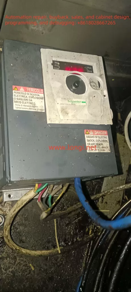
ATV12 physical working status

I. Overview of Schneider ATV12 Series Inverter

The Schneider ATV12 series inverter is a high-performance variable frequency drive widely used in various industrial settings. It offers a broad power range, high control precision, and significant energy savings. By communicating with the PLC, the inverter can achieve more flexible and efficient control, meeting the demands of complex industrial environments.

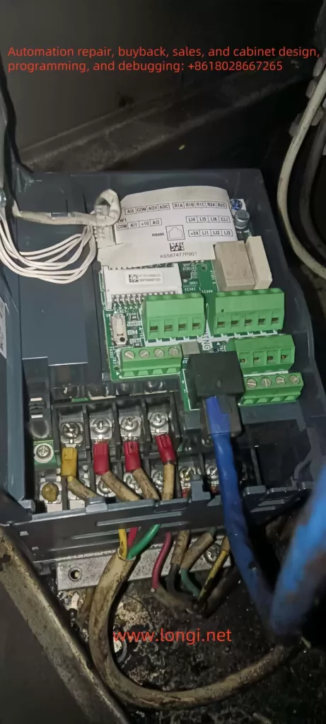
ATV12 communication wiring

II. Features of RS-485 Communication Protocol

RS-485 is a half-duplex communication protocol commonly used in industrial automation. Its key features include:

  1. Long-Distance Transmission: RS-485 supports long-distance data transmission, up to 1200 meters, making it suitable for large industrial sites.
  2. Multi-Drop Communication: It supports multiple devices on the same bus, ideal for complex industrial control networks.
  3. Strong Anti-Interference Capability: Using differential signaling, RS-485 offers strong anti-interference capabilities, suitable for environments with significant electromagnetic interference.
PLC communication wiring

III. Specific Wiring between Schneider ATV12 Inverter and PLC

To implement 485 communication between the Schneider ATV12 inverter and PLC, follow these steps:

  1. Preparation:
  • Ensure that the power to both the inverter and PLC is turned off for safety.
  • Prepare the RS-485 communication cable, typically a shielded twisted pair.
  1. Inverter-Side Wiring:
  • Locate the communication port on the Schneider ATV12 inverter labeled “RDA+” and “RDA-”.
  • Connect the two signal wires of the RS-485 cable to the “RDA+” and “RDA-” terminals.
  • Ground the cable shield to enhance anti-interference capability.
  1. PLC-Side Wiring:
  • On the PLC’s 485 communication module, find the corresponding “A” and “B” terminals.
  • Connect the RS-485 cable from the inverter to the “A” and “B” terminals on the PLC.
  • Ground the cable shield.
  1. Termination Resistor Matching:
  • Add a 120-ohm termination resistor at each end of the bus to eliminate signal reflections and ensure communication quality.

IV. Communication Features of Schneider ATV12 Inverter

The Schneider ATV12 series inverter has the following communication features:

  1. Multi-Protocol Support: Supports multiple communication protocols such as Modbus RTU, accommodating various industrial control requirements.
  2. High Reliability: Built-in EMC filters reduce electromagnetic interference, enhancing communication reliability.
  3. Flexible Configuration: Communication parameters such as baud rate and address can be flexibly configured to meet different communication needs.

V. Implementation Method

  1. Parameter Configuration:
  • Enter the inverter’s configuration mode and set communication parameters, including baud rate, data bits, parity, and stop bits.
  • Ensure that the communication parameters match those of the PLC to enable correct data transmission.
  1. Communication Testing:
  • After powering on, use the PLC’s communication software or programming tools to test the connection with the inverter.
  • Verify that data transmission is correct and that the inverter responds accurately to the PLC’s control commands.
  1. Function Verification:
  • In actual operation, verify the communication functionality between the inverter and PLC to ensure the motor operates as expected.
  • Adjust communication parameters and control strategies as needed to optimize system performance.
Touchscreen working status

VI. Conclusion

The Schneider ATV12 series inverter achieves efficient and reliable data exchange with the PLC through the RS-485 communication protocol, providing strong support for industrial automation control systems. Proper wiring and parameter configuration enable stable communication between the inverter and PLC, enhancing control precision and reliability. In practical applications, attention to communication line layout and shielding is crucial to ensure communication quality and minimize interference. Through thoughtful design and testing, the Schneider ATV12 inverter can leverage its high-efficiency control advantages in complex industrial environments.

Posted on Leave a comment

Causes and Solutions for the E0006 Fault in HPMONT HD09 Series Inverters

1. Fault Overview

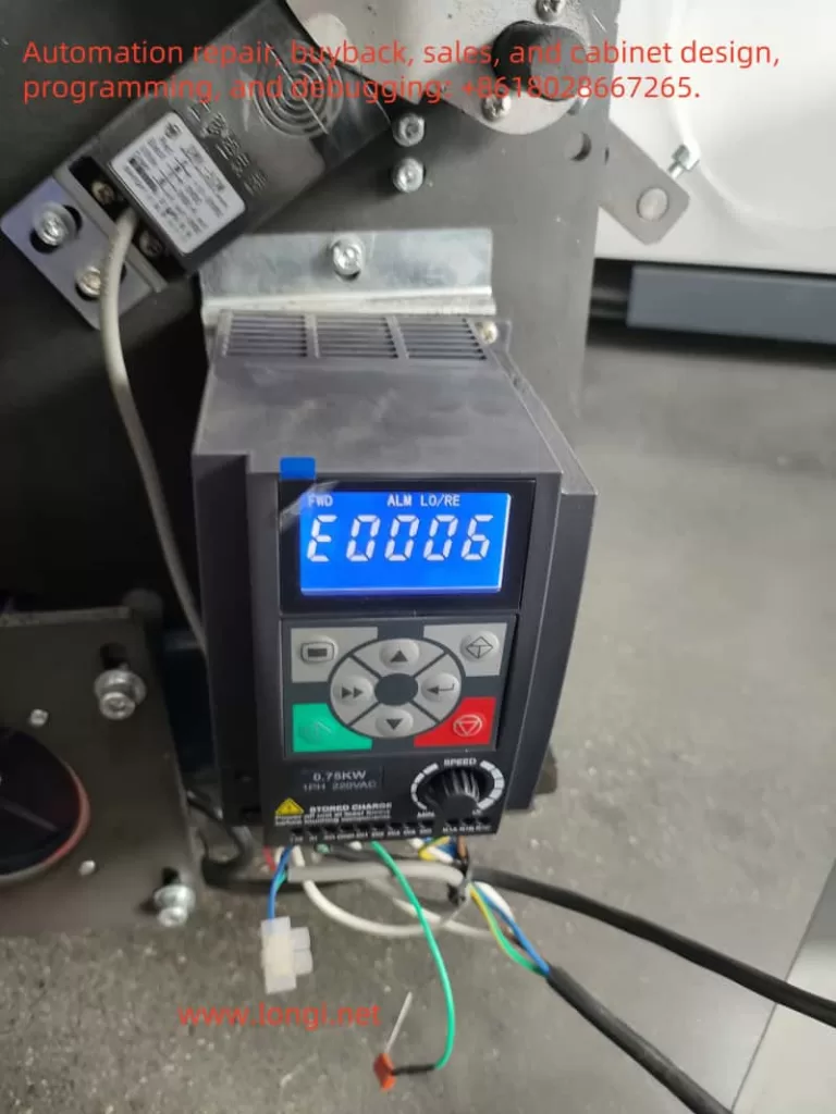
The E0006 fault in the HPMONT HD09 series inverter corresponds to a “DC bus constant-speed overvoltage fault.” This means that the DC bus voltage in the inverter exceeds the safety limit during constant-speed operation. Such faults can cause equipment shutdowns, affecting production and normal operation.

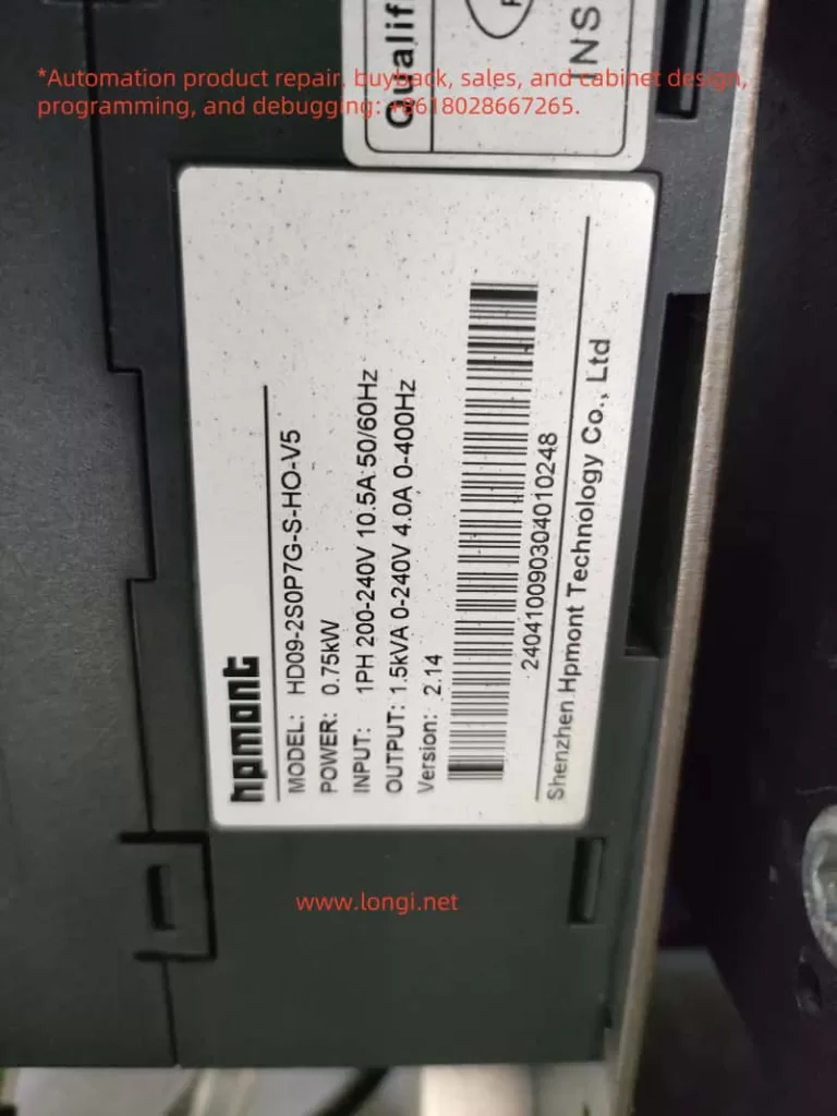
HP09 physical picture
oplus_32

2. Fault Mechanism Analysis

  1. Causes of DC Bus Overvoltage: The DC bus voltage in the inverter is converted from AC through a rectifier. If the input voltage is too high or too low, it can cause instability in the bus voltage. During load operation, especially during rapid stops, large load inertia, or abnormal braking systems, the DC bus voltage may rise sharply, triggering overvoltage protection.
  2. Constant-Speed Overvoltage Scenario: The inverter operates at a constant speed, maintaining a stable motor frequency. If the input power supply voltage is too high, or if the acceleration/deceleration times are improperly set, overvoltage can occur. Furthermore, if the braking system is improperly configured or not correctly installed, excessive voltage can be generated during deceleration.
  3. Potential Circuit Reasons:
    • High input voltage: Especially in areas where the grid voltage fluctuates significantly, the inverter may detect overvoltage.
    • Abnormal braking system: If the braking unit or brake resistor is incorrectly configured, or if it is not equipped in systems with heavy loads, excessive voltage can be generated during deceleration.
    • System overload: If the load is too heavy or has significant inertia, the inverter may not be able to decelerate effectively, leading to overvoltage faults.

3. On-Site Fault Handling Methods

  1. Check Input Voltage:
    • Use a multimeter to check whether the input voltage to the inverter is within the normal range. If the input voltage exceeds the specified range (e.g., too high), consider using a voltage regulator or check the stability of the power grid.
  2. Check Acceleration/Deceleration Time Settings:
    • Refer to the inverter’s user manual and check the acceleration and deceleration times (parameters such as F03.01, F03.02, etc.). Too short a deceleration time can cause a sharp fluctuation in the bus voltage. It is recommended to extend the deceleration time to avoid overvoltage.
  3. Check Braking System:
    • For loads requiring deceleration, inspect the braking unit and brake resistor configuration to ensure they are appropriately sized for the load. If necessary, add a braking unit or adjust the brake resistor’s power and resistance.
  4. Inspect and Check the Circuit:
    • Inspect the internal circuitry of the inverter for loose connections, poor contact, or damage, especially in the power and braking resistor wiring terminals.

4. Specific Circuit Repair Methods

  1. Input Voltage Issues:
    • If the input voltage is too high, consider adding measures to stabilize the grid power, such as using overvoltage protection devices. For areas with significant voltage fluctuations, it is recommended to use appropriate power protection equipment, such as overvoltage protectors.
  2. Braking System Faults:
    • If the braking system is causing overvoltage, first verify whether the braking resistor is correctly specified. If the braking resistor is inadequate or damaged, select a properly rated resistor according to the load requirements. Check that the braking unit is properly connected, and ensure the braking circuit is securely wired.
  3. Capacitor Issues:
    • If the capacitor is aging or damaged, it could cause the DC bus voltage to be unstable. In this case, replace the damaged capacitors and verify whether the capacitor’s capacity matches the requirements.
  4. Reconfigure Deceleration Time:
    • For loads with high inertia or large power, it is necessary to increase the deceleration time. This can be achieved by adjusting parameters such as F03.02 to prevent overvoltage faults. Ensure that the deceleration process is smooth and does not lead to a sharp voltage change.
E6000
oplus_32

5. Conclusion

The E0006 fault is typically caused by high input voltage, braking system issues, or improper acceleration/deceleration time settings. When addressing this fault, it is essential to check key parameters such as input voltage, acceleration/deceleration times, and the braking system. Specific circuit repair actions, such as replacing capacitors, adjusting the braking system configuration, and extending deceleration times, can restore normal operation of the inverter.

Posted on Leave a comment

User Manual Guide for Bosch Rexroth VFC3610/VFC5610 Series Frequency Converters

The Bosch Rexroth VFC3610/VFC5610 series frequency converters are high-performance devices widely used in industrial automation, mechanical processing, pump and fan control, and other fields. This article provides a detailed guide on using the user manual for these frequency converters, including operating panel functions, parameter settings, and troubleshooting.

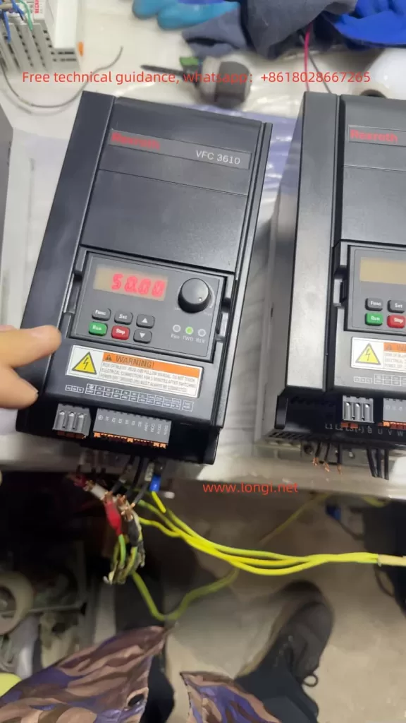
VFC3610VFC5610 physical picture

I. Operating Panel Function Introduction

1.1 Operating Panel Functions

The operating panel of the Bosch Rexroth VFC3610/VFC5610 series offers a range of functions for parameter settings, monitoring, and diagnostics. The main components include an LED display, navigation knob, function button, stop button, and run button.

  • LED Display: Shows the operating status, parameter values, and fault codes.
  • Navigation Knob: Used to select parameter groups/parameters and set parameter values.
  • Function Button (Func): Enters the parameter group screen and returns to the previous screen.
  • Stop Button (Stop): Stops the frequency converter.
  • Run Button (Run): Starts the frequency converter.

1.2 Parameter Copying

Users can copy parameter settings from one frequency converter to another using the parameter copy function:

  1. Back up parameters to the operating panel: Set parameter [b0.11] = ‘1: Backup parameters to the operating panel’.
  2. Install the operating panel on the target frequency converter.
  3. Set parameter [b0.11] = ‘2: Copy parameters from the operating panel’ to complete the parameter copying process.

1.3 Password Setting and Removal

To protect parameter settings, users can set a password. The steps for setting and removing the password are as follows:

  • Set Password: Set parameter [b0.20] to the desired user password (range: 0…65,535).
  • Remove Password: Set parameter [b0.20] to 0.

1.4 Parameter Access Restriction

To prevent unauthorized access to parameter settings, the frequency converter offers access restriction features. Users can set parameter [b0.00] to limit access rights:

  • 0: Basic parameters
  • 1: Standard parameters
  • 2: Advanced parameters
  • 3: Startup parameters
  • 4: Modified parameters

1.5 Parameter Initialization

In some cases, users may need to initialize the frequency converter parameters to their default settings. The steps are as follows:

  1. Set parameter [b0.10] = ‘1: Restore default settings’.
  2. The frequency converter will automatically revert to the factory default settings.
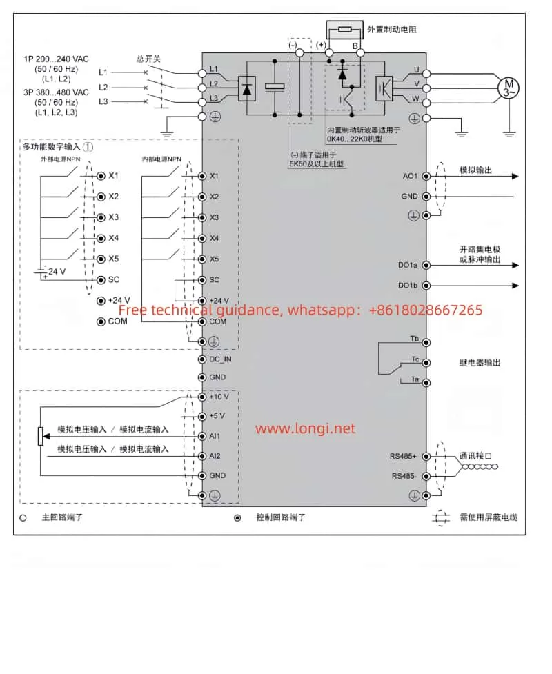
VFC3610_VFC5610 Standard Wiring Diagram

II. External Terminal Control and Speed Adjustment

2.1 External Terminal Forward and Reverse Control

Users can control the forward and reverse operations of the frequency converter through external terminals. The steps are as follows:

  1. Set parameter [E0.17] = ‘0: Forward / Reverse’.
  2. Connect the terminals:
  • X1: Multifunctional digital input for forward control.
  • X2: Multifunctional digital input for reverse control.

2.2 External Potentiometer Speed Adjustment

Users can adjust the speed of the frequency converter using an external potentiometer. The steps are as follows:

  1. Set parameter [E0.00] = ‘2: Al1 Analog Input’.
  2. Connect the terminals:
  • Al1: Analog voltage input for frequency setting.
  • GND: Common ground for analog input.

III. Fault Codes and Handling

3.1 Fault Codes

The Bosch Rexroth VFC3610/VFC5610 series provides detailed fault codes to help users quickly identify and resolve issues. Some common fault codes and their meanings are as follows:

  • 0: No fault
  • 1: OC-1, Overcurrent during constant speed
  • 2: OC-2, Overcurrent during acceleration
  • 3: OC-3, Overcurrent during deceleration
  • 4: OE-1, Overvoltage during constant speed
  • 5: OE-2, Overvoltage during acceleration
  • 6: OE-3, Overvoltage during deceleration
  • 7: OE-4, Overvoltage during stop
  • 8: UE-1, Undervoltage during operation
  • 9: SC, Current surge or short circuit
  • 10: IPH.L, Input phase loss
  • 11: OPH.L, Output phase loss
  • 12: ESS-, Soft start fault
  • 20: OL-1, Overload
  • 21: OH, Overheating
  • 23: FF, Fan failure
  • 24: Pdr, No-load protection
  • 25: Col:, Command value loss

3.2 Fault Handling

When a fault occurs, users should take appropriate actions based on the fault code’s meaning. For example:

  • Overcurrent Faults (1, 2, 3): Check if the motor and load are functioning correctly. Ensure proper cable connections and adjust parameter settings if necessary.
  • Overvoltage Faults (4, 5, 6, 7): Check if the power supply voltage is stable. Ensure proper cable connections and adjust parameter settings if necessary.
  • Undervoltage Fault (8): Check if the power supply voltage is normal. Ensure proper cable connections.
  • Short Circuit Fault (9): Check cable and terminal connections for short circuits.
  • Phase Loss Faults (10, 11): Check cable and terminal connections for phase loss.
  • Overload Fault (20): Check if the motor and load are functioning correctly. Ensure proper cable connections and adjust parameter settings if necessary.
  • Overheating Fault (21): Check the cooling conditions of the frequency converter. Ensure the fan is working properly and clean the heat sink if necessary.
  • Fan Failure (23): Check if the fan is working properly. Replace the fan if necessary.
  • No-load Protection (24): Check if the motor is running correctly and ensure the load is normal.
  • Command Value Loss (25): Check communication cables and terminals for proper connections. Ensure communication is functioning correctly.

Conclusion

The Bosch Rexroth VFC3610/VFC5610 series frequency converters are powerful and user-friendly devices suitable for various industrial control applications. This guide provides a comprehensive overview of the operating panel functions, parameter settings, and fault handling for these frequency converters. By following this guide, users can effectively operate and maintain these devices, enhancing productivity and reliability.

Posted on 1 Comment

Analysis and Handling of ER.258 Fault in Inovance IS620P Servo System

In industrial automation, servo systems play a crucial role in precise control and efficient driving tasks. However, in practical applications, servo systems may encounter various faults that affect the stability and efficiency of production lines. One of the common error codes in the Inovance IS620P servo system is ER.258, which can disrupt the normal operation of the system. This article will provide an in-depth analysis of the ER.258 fault, explore its causes, and suggest reasonable handling methods.

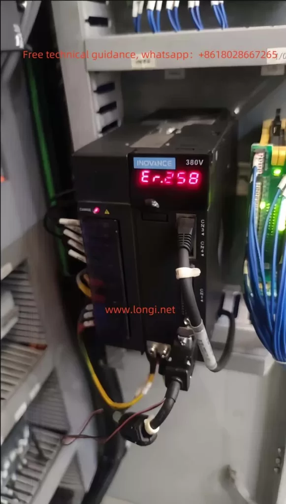
ER,258

1. Analysis of ER.258 Fault

1.1 Basic Meaning of ER.258 Fault

The ER.258 fault is typically associated with the speed, torque, and position control in the servo system during the return-to-zero process. According to the design of the Inovance IS620P servo, the return-to-zero process begins after the motor contacts the limit switch. When the motor hits the limit switch, if the motor’s speed and torque meet certain threshold values, the system considers that the motor has reached the limit position and triggers the return-to-zero operation. However, in some cases, if the motor’s speed and torque are out of the normal range, or the system fails to accurately determine if the motor has stopped, the ER.258 fault is triggered.

1.2 Conditions for the Fault to Occur

Specifically, the ER.258 fault is triggered in the following situations:

  • Overcurrent or Overload: When the motor contacts the limit switch, if the current suddenly increases, or if the resistance at the limit position is too high, causing the motor’s torque to exceed the allowed range, an overcurrent or overload protection alarm will be triggered.
  • Exceeding Position Limit: When the motor reaches the mechanical limit, if it continues to try to move or cannot stop properly, the system considers that the motor has exceeded the predefined position and triggers the alarm.
  • Motor Has Not Fully Stopped: When the H05-56 parameter is set too sensitively (such as setting it to 0), the system might wrongly interpret that the motor has stopped while it has not completely stopped, leading to the ER.258 fault.

1.3 Influence of H05-56 Parameter on the Fault

The H05-56 parameter plays an important role during the return-to-zero process. It sets the minimum speed threshold, and when the motor’s speed falls below this value, the system assumes that the motor has stopped and initiates the return-to-zero process. If H05-56 is set to 0, the system becomes overly sensitive in determining if the motor has stopped, which might lead to the motor not fully stopping, but the system falsely interpreting it as a stop and triggering the ER.258 fault.

1.4 Impact of Parameter Setting on the Fault

When the H05-56 parameter is set to 1, the system requires the motor’s speed to drop below 1 rpm before it determines that the motor has stopped and initiates the return-to-zero process. This provides more time and space for the motor to decelerate and avoids triggering the fault caused by speed instability or excessive torque. According to data, changes in the H05-56 parameter directly affect the system’s tolerance, ensuring that the motor and drive system will not cause overcurrent or excessive torque after contacting the limit switch, thus preventing the ER.258 fault.

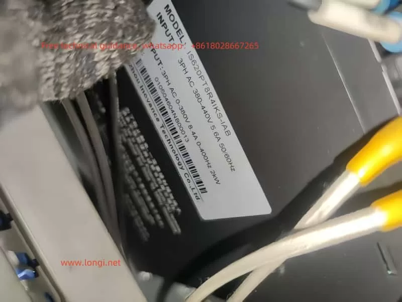
ISP620P

2. Causes of ER.258 Fault

2.1 Behavior of the Motor After Contacting the Limit Switch

During the return-to-zero process, the servo motor first contacts the mechanical limit switch. At this point, the motor’s torque and speed will be significantly affected. Once the motor contacts the limit switch, the system evaluates the motor’s speed and torque. If the torque exceeds a certain set value, the system assumes that the motor has reached the mechanical limit and stops further movement. If not, the motor may continue to attempt movement, leading to abnormal current or torque, triggering the ER.258 fault.

2.2 Incorrect Determination of Motor Stop Status

When the H05-56 parameter is set to 0, the system may mistakenly determine that the motor has stopped even if it has not completely stopped. This could happen because the motor might still have slight inertia or be moving slightly, causing the system to incorrectly interpret this as a stop condition and initiate the return-to-zero process prematurely, leading to the fault.

2.3 Excessive Current and Torque

After the motor contacts the limit switch, it may experience significant resistance or load, generating excessive torque. If the current exceeds the maximum allowable capacity of the drive, the system will trigger an overcurrent alarm, causing the ER.258 fault to occur.

2.4 Uneven Load or Slow Deceleration

If the motor’s load is uneven or the deceleration process is slow, the motor may continue to attempt movement after contacting the limit switch, generating excessive current or torque, triggering the ER.258 fault. Proper adjustment of the H05-56 parameter can help prevent this situation.

3. Handling Methods for ER.258 Fault

3.1 Adjusting the H05-56 Parameter

As mentioned earlier, the H05-56 parameter has a significant impact on the system during the return-to-zero process. Setting H05-56 to 1 can effectively prevent the ER.258 fault. This setting requires the motor’s speed to drop below 1 rpm before it is considered stopped, thus providing more time for the motor to decelerate and avoiding triggering the fault due to instability.

3.2 Checking Load and Torque

During the return-to-zero process, the motor’s load and torque can cause excessive current, triggering the ER.258 fault. Check whether the motor’s load and torque are too high and ensure that the motor can stop stably after contacting the limit switch. This will help avoid overcurrent or overload protection from being triggered.

3.3 Calibrating the Limit Switch

Check and calibrate the position of the mechanical limit switch to ensure that the motor stops at the correct position. Early or late contact with the limit switch could prevent the motor from stopping properly, leading to excessive torque and current, and triggering the ER.258 fault.

3.4 Adjusting the Motor’s Deceleration Settings

If the motor’s deceleration process is too slow, it may cause excessive torque or current, triggering the fault. Adjust the motor’s deceleration time and method to ensure that the motor decelerates smoothly after contacting the limit switch, avoiding excessive current and torque.

3.5 Regular Maintenance and Inspection

Regularly inspect the operation status of the servo system, including the motor, drive, limit switches, and other components. Clean the mechanical parts from dirt and check the motor’s operating condition to ensure that the system operates within normal ranges and prevent faults due to wear or malfunction.

4. Conclusion

The ER.258 fault is a common alarm in the Inovance IS620P servo system during the return-to-zero process. It is usually related to motor speed, torque, position control, and the functioning of the limit switch. By adjusting the H05-56 parameter, checking the load and torque, calibrating the limit switch, optimizing the motor deceleration settings, and performing regular maintenance, the occurrence of the ER.258 fault can be effectively prevented. Proper system settings and regular maintenance ensure the stable operation of the servo system, improving the reliability and efficiency of the equipment.

Posted on Leave a comment

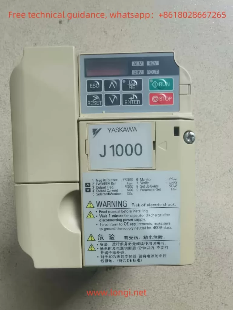
Analysis and Solutions for the Uu1 Fault in Yaskawa J1000 Series Inverters

The Yaskawa J1000 series inverters are widely used in industrial automation for their stable control performance and high energy efficiency. However, during actual operation, inverters may encounter various faults, one of which is the “Uu1” fault. This article will analyze the meaning, causes, and solutions for the Uu1 fault from both external and internal perspectives, providing a reference for inverter maintenance and repair.


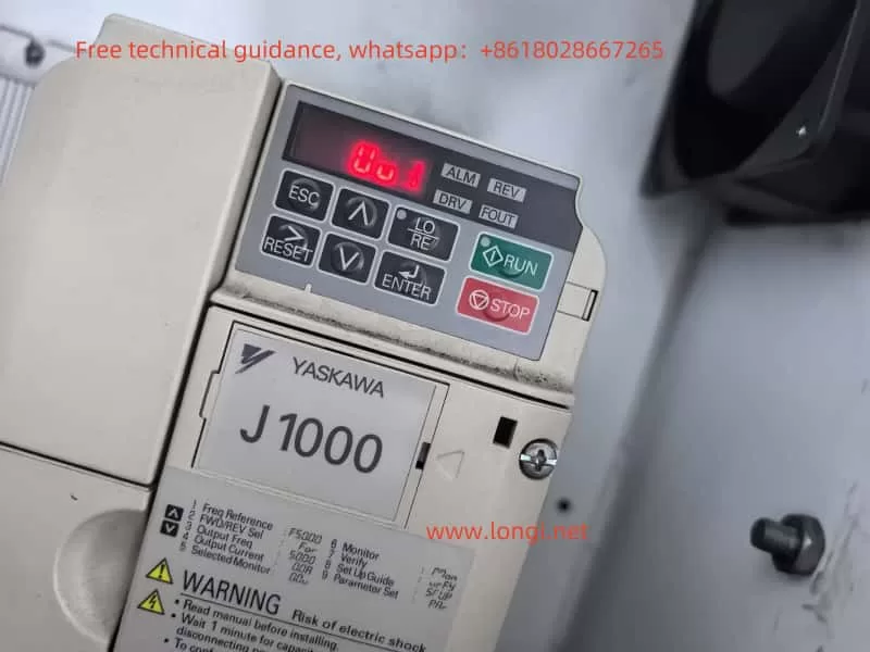
J1000 displays Uu1 fault

I. Meaning and Causes of the Uu1 Fault

1. Fault Meaning

The Uu1 fault indicates an undervoltage output fault, meaning the inverter detects that the output voltage is below the set minimum value, triggering a protective mechanism. This fault often causes the inverter to stop, protecting the motor and load from potential damage.

2. Causes of the Fault

The Uu1 fault can be attributed to several factors:

  • Unstable power supply: The input voltage to the inverter is lower than the rated range, leading to insufficient output voltage.
  • Wiring issues: Poor contact in the input or output wiring causes voltage drops.
  • Internal inverter faults: Damage to the inverter’s internal circuits or components results in abnormal output voltage.
  • Motor or load faults: Issues with the motor or load cause abnormal feedback voltage.

3. On-Site Handling Methods

To address the Uu1 fault on-site, follow these steps:

  1. Check the power supply voltage: Use a voltmeter to measure the inverter’s input voltage and ensure it is within the rated range. If the voltage is too low or unstable, inspect the power supply, and replace it or use a voltage stabilizer if necessary.
  2. Inspect the wiring: Check the input and output wiring for proper contact, ensuring no loose or disconnected wires. If poor contact is found, reconnect the wiring and tighten the screws.
  3. Examine the inverter internally: If the power supply and wiring are fine, the issue may lie within the inverter. Consult a professional technician or the manufacturer for repairs.
  4. Check the motor and load: Ensure the motor is operating normally and inspect the load for any issues.
  5. Reset the fault: After resolving the issue, press the RESET button on the inverter to clear the fault. Restart the inverter and observe its operation.

II. Analysis of Electrical Issues from the Inverter’s Internal Structure

1. Overview of the Inverter’s Internal Structure

The internal structure of the Yaskawa J1000 series inverter primarily includes the rectifier circuit, inverter circuit, control circuit, and protection circuit. The rectifier circuit converts AC voltage to DC voltage, the inverter circuit converts DC voltage to variable-frequency AC voltage, the control circuit regulates the output frequency and voltage, and the protection circuit detects and protects against faults such as overload, overvoltage, and overcurrent.

2. Electrical Issues Related to the Uu1 Fault

The Uu1 fault is typically associated with the inverter’s output circuit and involves the following aspects:

  • Rectifier circuit faults: Damage to diodes or capacitors in the rectifier circuit can lead to insufficient DC voltage, affecting the output voltage.
  • Inverter circuit faults: Damage to IGBT modules or driver circuits in the inverter circuit can cause abnormal output voltage.
  • Control circuit faults: Faults in the microprocessor or driver chips in the control circuit can result in inaccurate output voltage regulation.
  • Protection circuit faults: Malfunctioning detection components or protection chips in the protection circuit can lead to incorrect identification of undervoltage.

3. Electrical Repair Methods

To repair the Uu1 fault, follow these steps:

  1. Inspect the rectifier circuit: Use a multimeter to test the diodes and capacitors in the rectifier circuit to ensure they are functioning correctly. Replace any damaged components.
  2. Check the inverter circuit: Inspect the IGBT modules and driver circuits for proper operation. Replace any faulty modules or chips.
  3. Examine the control circuit: Test the microprocessor and driver chips to ensure they are functioning correctly. Replace any faulty chips.
  4. Inspect the protection circuit: Check the detection components and protection chips in the protection circuit for proper operation. Replace any faulty components.

J1000 physical image

III. Comprehensive Solutions for the Uu1 Fault

1. Preventive Measures

To prevent the occurrence of the Uu1 fault, consider the following measures:

  • Regularly check the power supply voltage: Periodically inspect the inverter’s input voltage to ensure stability.
  • Maintain wiring connections: Regularly check the wiring for proper contact and address any issues promptly.
  • Inspect the inverter internally: Periodically check the inverter’s internal circuits to identify and resolve potential faults early.
  • Maintain the motor and load: Regularly inspect the motor and load to ensure they are operating correctly.

2. Fault Handling Procedure

When addressing the Uu1 fault, follow this procedure:

  1. Confirm the fault: Verify the Uu1 fault on the inverter’s display.
  2. Check the power supply voltage: Ensure the input voltage is normal.
  3. Inspect the wiring: Check for proper wiring connections.
  4. Examine the inverter internally: Ensure the internal circuits are functioning correctly.
  5. Check the motor and load: Verify that the motor and load are operating normally.
  6. Reset the fault: After resolving the issue, reset the inverter and observe its operation.

3. Professional Support

If the Uu1 fault cannot be resolved through the above methods, consult a professional technician or the manufacturer for further assistance.


Conclusion

The Uu1 fault in the Yaskawa J1000 series inverters is a common undervoltage output fault with complex causes, involving the power supply, wiring, internal circuits, motor, and load. Through systematic fault analysis and step-by-step troubleshooting, the Uu1 fault can be effectively resolved, ensuring stable inverter operation. Regular maintenance and preventive measures are also crucial in avoiding such faults.