
I. Fault Phenomenon and Definition
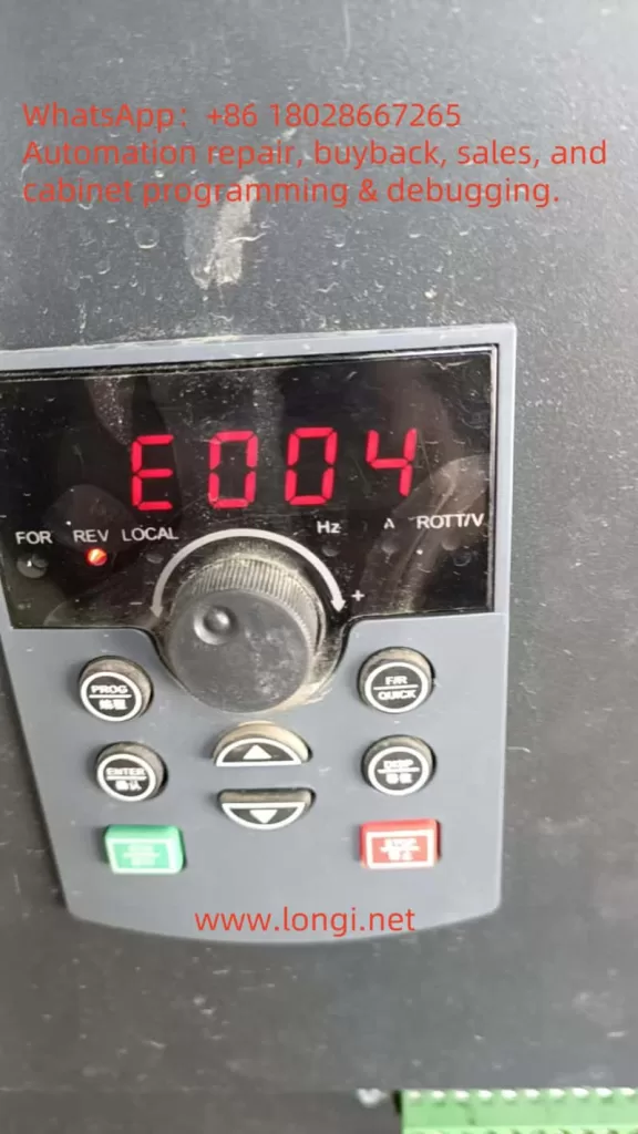
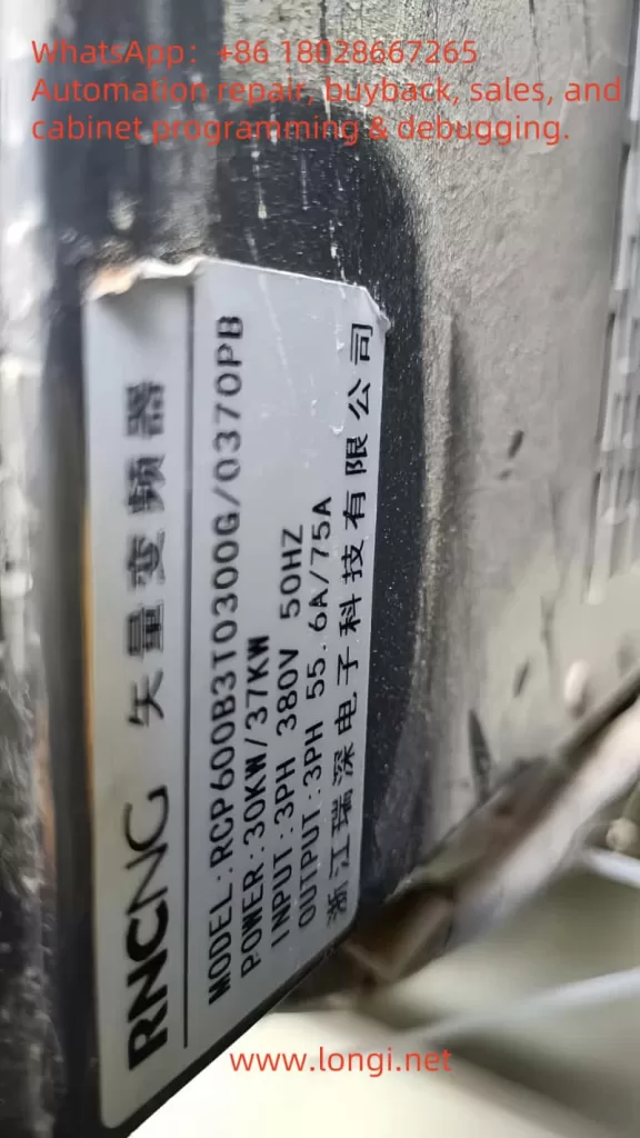
ERR04 is a common fault code for the Ruishen RCP600 series inverter during operation, indicating a constant speed overcurrent issue. This fault is triggered when the inverter detects that the output current continuously exceeds 150% to 200% of the rated value during the constant speed stage (non-acceleration/deceleration process). The fault phenomena include:
- Display of “ERR04” or “Constant Speed Overcurrent” alarm on the inverter panel.
- Equipment shutdown protection, possibly accompanied by abnormal noise or motor overheating.
- The fault can be reset for brief operation but tends to recur.
This fault directly affects the continuous operation capability of the equipment and requires systematic troubleshooting from three aspects: electrical parameters, mechanical load, and hardware status.
II. Fault Cause Analysis and Diagnostic Process
1. Classification of Core Causes
| Category | Specific Causes |
|---|---|
| Parameter Settings | Mismatch of motor parameters (e.g., rated current, number of poles), over-aggressive PID tuning, excessive torque compensation |
| Load Anomalies | Mechanical jamming, sudden load changes (e.g., drive mechanism failure), increased resistance due to motor bearing damage |
| Electrical Faults | Output side short circuit/ground fault, cable insulation aging, current detection circuit anomalies (e.g., Hall sensor drift or damage) |
| Cooling Issues | Poor heat dissipation leading to degraded IGBT module performance and reduced carrier capability |
2. Scientific Diagnostic Process
Step 1 – On-site Observation and Data Recording
- Record the operating frequency, current value, and DC bus voltage (readable via the panel’s U0 parameter group) at the time of fault occurrence.
- Check for abnormal noises, temperature rise, or visible mechanical damage in the motor and mechanical load.
Step 2 – Distinguishing Between Load-Side and Electrical-Side Faults
- Disconnect the motor load and run the inverter under no load: If ERR04 disappears, the issue is on the load side; if it persists, check electrical parameters and hardware.
- Use a megohmmeter to test the motor winding insulation to ground (requirement: ≥5MΩ) to rule out ground faults.
Step 3 – Parameter Verification and Waveform Analysis
- Verify the motor nameplate parameters and check if the P0 group (basic parameters) and A2 group (motor parameters) settings match the actual motor.
- Observe the output current waveform for distortions (e.g., excessive harmonics) using an oscilloscope or the inverter’s built-in waveform recording function.
III. Targeted Solutions
1. Parameter Optimization and Adjustment
- Motor Self-Learning: Perform the inverter’s “Motor Parameter Auto-Tuning” (refer to the PA group function in the manual) to ensure stator resistance and inductance values match the actual motor.
- Reduce Torque Compensation: Adjust the P2-21 parameter (constant speed torque compensation coefficient) and gradually reduce it to 80% to 100% for testing.
- PID Parameter Reset: If PID control is applied, reset the PA-03 (proportional gain) and PA-04 (integral time) to their default values to avoid over-tuning.
2. Load-Side Fault Handling
- Mechanical System Inspection: Check coupling alignment, bearing lubrication, and belt tension to eliminate jamming points.
- Load Matching Verification: Ensure the motor power matches the mechanical load to avoid long-term overload operation. For example, a 22kW motor driving a 30kW load requires an upgraded inverter and motor combination.
3. Electrical Hardware Maintenance
- Output Side Insulation Test: Use a 500V megohmmeter to measure the U/V/W terminal insulation to ground. If <5MΩ, replace the motor cable or repair the winding.
- Current Detection Calibration:
- Check for loose Hall sensor connections.
- Recalibrate the current detection accuracy using the AC-20 to AC-27 parameters (analog calibration parameters), with a tolerance deviation within ±2%.
- Cooling System Maintenance: Clean the air duct dust, test the cooling fan operation (set temperature threshold via P8-47), and replace aged fans if necessary.
4. Advanced Debugging Techniques
- Carrier Frequency Adjustment: Reduce the carrier frequency in the A5-01 parameter (PWM modulation method) (e.g., from 12kHz to 8kHz) to reduce switching losses and temperature rise.
- Overcurrent Stall Suppression: Enable the P3-19 (overcurrent stall control) and P3-20 (suppression intensity) parameters, setting the action current to 130% to 150% of the rated value.
IV. Preventive Maintenance Recommendations
- Regular Parameter Backup: Utilize the inverter’s “User Parameter Backup” function (P7 group) to save optimized parameters and prevent失调due to accidental resets.
- Hardware Inspection Regimen:
- Quarterly inspection of output terminal tightness to prevent increased contact resistance.
- Annual thermal imaging scan of IGBT modules and rectifier bridges to address abnormal temperature rise points.
- Load Monitoring: Install mechanical vibration sensors and current trend recorders for early fault warnings.
V. Maintenance Case Reference
Case Background: An RCP600-22kW inverter for an injection molding machine frequently reported ERR04, operating normally under no load but triggering the fault after 10 minutes under load.
Troubleshooting Process:
- No-load current was 12A (normal), but under load, it rose to 48A (rated current 42A).
- Motor insulation test was normal, but disassembly revealed rusted and jammed reducer bearings.
- After replacing the bearings and adjusting the P2-21 parameter (torque compensation) from 150% to 110%, the fault was resolved.
VI. Summary
Resolving the ERR04 fault requires a three-tiered troubleshooting approach focusing on “parameters, load, and hardware,” combined with real-time data and equipment status analysis. The key is to distinguish between transient overcurrent and sustained overload, avoiding unnecessary component replacements. Through scientific debugging processes and preventive maintenance, the stability of the inverter system can be significantly improved, reducing the risk of unplanned downtime.