
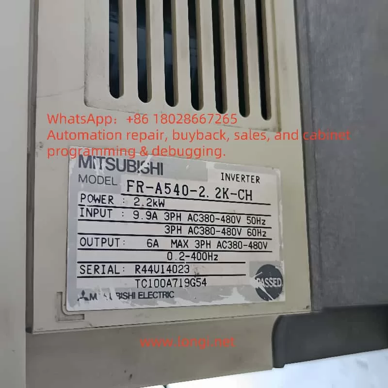
The Mitsubishi FR-A500 series inverter, including models A540 and A520, is a widely used device in the field of industrial control. Its user manual serves as an essential guide for operating and maintaining the inverter. This article provides a detailed introduction to the operation panel functions, parameter settings, password management, external control, and fault handling of this series of inverters based on the user manual.
I. Introduction to Operation Panel Functions
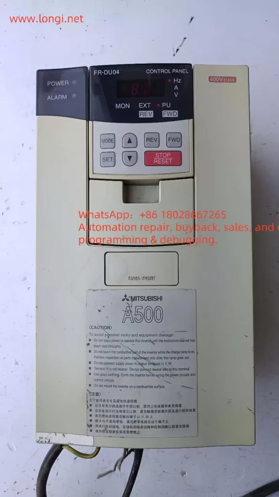
The operation panel (FR-DU04) of the Mitsubishi FR-A500 series inverter is the primary interface for users to interact with the inverter, offering a range of display and operation capabilities:
- Display Functions: The operation panel can display real-time key parameters of the inverter, such as operating frequency, output current, output voltage, and alarm information, facilitating user monitoring of the inverter’s status.
- Key Functions:
MODEKey: Used to switch between different operation modes, such as monitor mode, frequency setting mode, and parameter setting mode.SETKey: Used to confirm set values or enter the parameter setting interface.↑and↓Keys: Used to increase or decrease set values, adjusting parameters or frequencies.FWDandREVKeys: Used to issue forward and reverse commands, respectively, controlling the motor’s rotation direction.STOP RESETKey: Used to stop the inverter or reset faults.
II. Parameter Initialization Settings
During the use of the inverter, it may be necessary to restore parameters to their factory settings. Users can perform parameter initialization through the following steps:
- Clear All Parameters: Set parameter
Pr.77to1, then press and hold theSETkey for more than 1.5 seconds to restore all parameters (exceptPr.77,Pr.79,Pr.80, andPr.81) to their factory settings. - Clear User Parameter Groups: To clear user-defined parameter groups, use parameters
Pr.174andPr.176to clear the first and second user parameter groups, respectively.
III. Password Setting, Removal, and Parameter Access Restrictions
To protect the inverter’s parameters from being modified arbitrarily, users can set parameter access restrictions through the following methods:
- Parameter Write Protection Selection (Pr.77):
- When set to
1, parameters can only be written when the inverter is stopped. - When set to
2, writing to all parameters is prohibited (factory setting). - When set to
0, parameter writing is allowed during operation (note: safety considerations apply).
- When set to
- Password Function: Although the FR-A500 series inverter does not directly provide a password setting function, parameter write protection through
Pr.77can indirectly achieve a certain level of access control.
IV. External Control Functions
The Mitsubishi FR-A500 series inverter supports external terminal control, allowing users to configure it flexibly according to actual needs.
- External Terminal Forward/Reverse Control:
- Use terminals
STF(forward start) andSTR(reverse start) for forward/reverse control. When theSTFsignal is activated, the inverter operates in the forward direction; when theSTRsignal is activated, it operates in reverse. - Parameter Settings: Ensure that
Pr.79(operation mode selection) is set to external operation mode or combined operation mode to enable external terminal control.
- Use terminals
- External Potentiometer for Frequency Setting and Speed Control:
- Frequency Setting Terminals: Use terminals
2,4,5, and10(orAUterminal, depending on parameter settings) for analog frequency setting. Typically, a potentiometer is connected between terminals10(orAU) and5, and the input voltage is adjusted by rotating the potentiometer to set the operating frequency. - Parameter Settings: Set
Pr.73to select the voltage input range (e.g.,0-5V,0-10V, etc.); ensure that parameters such asPr.125(analog input filter time constant) are set appropriately to ensure the stability of frequency setting.
- Frequency Setting Terminals: Use terminals
V. Fault Codes and Handling Methods
The inverter may encounter various faults during operation, and the user manual provides detailed fault codes and handling methods. Below are some common fault codes and brief handling steps:
- E.OC1 (Overcurrent Trip During Acceleration): Check if the load is too heavy, if the acceleration time is too short, and if the motor and cable insulation are in good condition.
- E.OV1 (Regenerative Overvoltage Trip During Acceleration): Check if the power supply voltage is too high, if the deceleration time is too short, and if the braking resistor is damaged.
- E.THM (Motor Overload Trip): Check if the motor load is too heavy, if the motor cooling is adequate, and if necessary, reduce the load or improve the cooling conditions.
- E.UVT (Undervoltage Protection): Check if the power supply voltage is too low and if the power lines are properly connected.
- E.FIN (Heat Sink Overheat): Check if the inverter’s heat sink is excessively dusty, if ventilation is adequate, and if necessary, clean the heat sink or improve ventilation conditions.
When the inverter stops due to a fault, the operation panel displays the corresponding fault code. Users should refer to the user manual based on the fault code and take appropriate handling measures. After handling, press the STOP RESET key to reset the inverter and restart operation.
VI. Conclusion
The Mitsubishi FR-A500 (A540 and A520) series user manual is an essential guide for operating and maintaining the inverter. Through this article, users should be able to master the operation skills of the operation panel functions, parameter initialization settings, password management, external control, and fault handling. In practical applications, users should configure the inverter parameters reasonably according to specific needs to ensure stable and efficient operation of the inverter. Additionally, regularly consulting the user manual to stay informed about the latest features and technical advancements of the inverter is also an important way to enhance equipment management capabilities.