Introduction
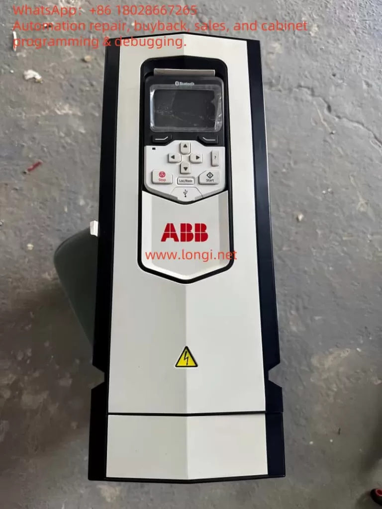
The ABB ACS880 series of variable frequency drives (VFDs) is a high-performance solution widely utilized in industrial automation for motor control, energy optimization, and process automation. Renowned for its reliability and flexibility, it is a preferred choice across various industries. However, during operation, VFDs may encounter fault alarms triggered by internal or external factors, with fault code 9081—”External Fault 1″—being one of the more frequent issues. When this fault occurs, the VFD typically halts operation, leading to production interruptions, making swift problem identification and resolution critical.
This article draws on the ACS880 Firmware Manual (version 3AUG0509 005, released August 1, 2013) and the fault details you provided to conduct an in-depth analysis of fault 9081. It explores its causes, impacts on the system, and offers detailed troubleshooting steps, solutions, and preventive recommendations. Our goal is to equip you with a thorough understanding of this fault, enabling you to restore normal operation efficiently in practical scenarios.

1. Definition and Background of Fault 9081
According to the “Fault Tracing” section on page 299 of the ACS880 Firmware Manual, fault code 9081 is defined as “External Fault 1.” This is a protective fault triggered by an external input signal, indicating that the VFD has received a fault signal via a digital input (DI) terminal or fieldbus, suggesting a potential risk to the system. The manual specifies that this fault is closely tied to parameter 31.01 (External Fault 1 Signal Source), which allows users to designate the source of the fault signal, such as a specific digital input (DI1 to DI6) or a designated bit in the fieldbus control word.
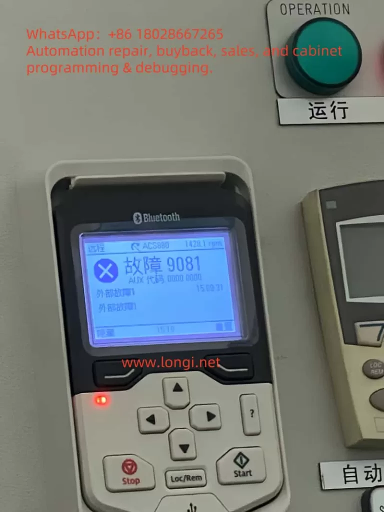
Based on the fault description you provided, the ACS880 control panel displays “Fault 9081 AUX Code 0000 0000” with “External Fault 1” noted. The auxiliary code (AUX Code) is all zeros, indicating no additional sub-fault details are available. The panel also shows an operating speed of 1420 rpm, a timestamp of 15:09:31, a “Remote” status, and an illuminated red fault indicator, confirming the device has entered a stopped state. This information serves as a valuable starting point for further analysis.
The External Fault 1 feature is designed to protect the VFD and its connected load from external anomalies. By configuring parameters, users can link the status of external devices (e.g., sensor alarms, PLC signals) to the VFD’s protective mechanisms. However, this also means that the root cause of fault 9081 may lie outside the VFD itself, in the external environment or configuration.
2. Possible Causes of Fault 9081
Drawing from the manual and real-world industrial scenarios, the causes of fault 9081 can be categorized as follows:
2.1 External Device Malfunction
The most common cause of External Fault 1 is a failure in an external device connected to the VFD. For instance, a temperature sensor detecting motor overheating, a pressure switch triggered by system overpressure, or an emergency stop button being inadvertently pressed could send a high-level signal via a digital input (e.g., DI1) to trigger the fault.
2.2 Wiring Issues
Faulty wiring at the digital input terminals is another frequent culprit. Loose, broken, or short-circuited connections can disrupt signal transmission. For example, damage to the DI1 signal line or poor contact might lead the VFD to misinterpret the state as a fault. Additionally, unshielded signal cables may be susceptible to electromagnetic interference (EMI), causing signal jitter or false triggers.
2.3 Incorrect Parameter Settings
Parameter 31.01 defines the signal source for External Fault 1. Misconfiguration, such as assigning an unused terminal (e.g., DI2) as the source or failing to match the external device’s logic state (high or low), can result in erroneous alarms. For fieldbus-triggered faults, parameters 50.01 (FBA A Enable) and 51.27 (FBA Parameter Update) must also be correctly set.
2.4 External Power or Control System Issues
Instability in the external device’s power supply or anomalies in the control logic can also trigger the fault. For example, a programming error in a PLC might cause it to send an unintended fault signal to the VFD, or voltage fluctuations in the external power supply could affect sensor operation.
2.5 Environmental Factors
Harsh industrial environments (e.g., high temperatures, humidity, dust) can impact the reliability of external devices or wiring. For instance, a sensor might malfunction under high heat, or corroded terminal connections could fail, triggering External Fault 1.

3. Impact of Fault 9081
Once fault 9081 is triggered, the VFD executes a default protective action based on parameter 31.11 (Fault Reset Selection), typically an immediate shutdown. This stops the motor, disrupting production line continuity and efficiency. If left unresolved, the fault may lead to further issues:
- Production Downtime: Line stoppages can result in significant economic losses, particularly in continuous production settings.
- Safety Risks to Equipment: Failure to identify and address the external fault could lead to more severe system damage.
- Increased Maintenance Costs: Recurring faults may require additional troubleshooting and repair time.
Thus, promptly and accurately resolving fault 9081 is essential.
4. Troubleshooting Steps
To effectively address fault 9081, follow these systematic troubleshooting steps:
4.1 Review Control Panel Information and Event Log
Begin by recording the fault details on the control panel (time, speed, status, etc.). Then, access the “Event Log” menu via the control panel or Drive Composer PC tool to review detailed fault logs. Page 300 of the manual notes that the event log stores the fault occurrence time and other parameters, aiding in identifying the trigger conditions.
4.2 Verify Parameter 31.01 Settings
Navigate to the parameter settings menu and check the configuration of parameter 31.01:
- If set to a digital input (e.g., DI1), note the terminal and inspect its wiring and signal state.
- If set to a fieldbus signal, verify the communication status and control word configuration.
4.3 Inspect External Devices and Wiring
Based on parameter 31.01, examine the corresponding external device and wiring:
- Use a multimeter to measure the voltage at the digital input terminal, confirming whether it is high (typically 24V indicating a fault state).
- Check for secure connections, ruling out looseness, breaks, or shorts.
- Ensure signal cables are properly shielded to avoid electromagnetic interference.
4.4 Investigate External Control Systems
For fieldbus-triggered faults, inspect the PLC or upper-level controller’s program logic to ensure no erroneous fault signals are sent. Verify that communication parameters (e.g., 50.01 and 51.27) are correctly configured.
4.5 Mitigate Environmental Effects
Assess the operating environment for issues like high temperature, humidity, or dust. If conditions are adverse, implement protective measures such as installing covers or improving ventilation.
4.6 Review Historical Fault Records
Check parameter group 04 (Warnings and Faults) for the current fault (04.01) and historical records (04.02 to 04.06) to determine if the fault recurs or is linked to other issues.
5. Resolution Methods
Based on the troubleshooting results, apply the following targeted solutions:
5.1 Repair External Devices
If a sensor or switch is faulty (e.g., triggered by overheating), repair or replace the defective component to restore normal signal output.
5.2 Address Wiring Problems
Re-secure loose connections or replace damaged cables. If interference is present, use shielded cables and ensure proper grounding.
5.3 Adjust Parameter Settings
If parameter 31.01 is misconfigured, adjust it to the correct signal source or temporarily disable the External Fault function (set to “Not Used”) to isolate the issue. For fieldbus users, ensure parameters 50.01 and 51.27 are correctly set before restarting the device.
5.4 Fault Reset and Testing
Per page 299 of the manual, fault reset can be performed via the control panel, digital input, or fieldbus. Press the “Reset” key on the control panel or configure parameter 31.11 for automatic reset. After resetting, restart the VFD and monitor its operation.
5.5 Seek Technical Support
If the issue persists, page 349 of the manual recommends contacting ABB technical support. Provide the device model (ACS880), firmware version (3AUG0509 005), and fault code (9081) for professional assistance.
6. Prevention Measures and Long-Term Maintenance Recommendations
To prevent recurrence of fault 9081, consider the following preventive actions:
6.1 Regular Inspection and Maintenance
Establish a maintenance schedule to periodically check wiring terminals and external device conditions, preventing aging or damage.
6.2 Optimize Parameter Configuration
Document all parameter settings during commissioning, ensuring that 31.01 and related parameters align with the application to avoid misconfiguration.
6.3 Improve Operating Environment
Maintain suitable temperature and humidity conditions for equipment operation, reducing environmental impacts on external devices.
6.4 Enhance System Monitoring
Use Drive Composer tools or fieldbus for real-time monitoring of VFD status, enabling early detection of anomalies.
6.5 Train Operating Personnel
Provide training on ACS880 operation and fault handling to enhance staff responsiveness.
7. Conclusion
ACS880 fault 9081 “External Fault 1” is a common externally triggered fault, often caused by external device malfunctions, wiring issues, parameter errors, or environmental factors. By reviewing control panel data, parameter settings, wiring, and external devices, users can quickly pinpoint the root cause and resolve it through repairs, adjustments, or resets. Regular maintenance and optimization measures can significantly reduce fault occurrences, ensuring long-term equipment stability.
The ABB ACS880 VFD is celebrated for its efficiency and reliability, and effectively managing fault 9081 not only restores production but also maximizes its value in industrial automation. For complex cases, seeking timely support from ABB is a wise decision. We hope this article’s analysis and recommendations provide practical guidance to enhance your equipment management and production efficiency.
