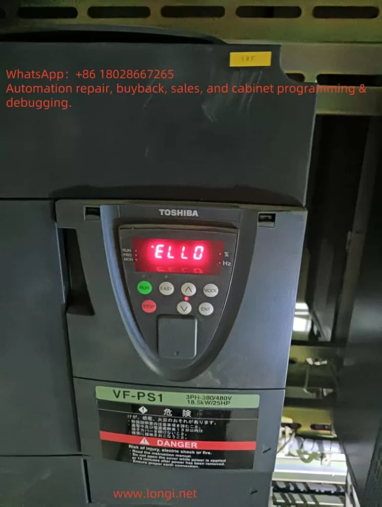
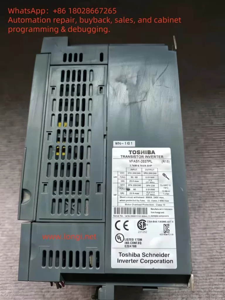
In the field of industrial automation, inverters play a crucial role in driving motors and optimizing energy efficiency. The Toshiba VF-PS1 series is known for its reliability and versatility across a wide range of applications such as manufacturing, HVAC systems, and water treatment. However, during a recent on-site startup, an unusual issue occurred: the inverter powered up and the screen continuously displayed “ELL0”, while all indicator LEDs on the operation panel (RUN, Hz, %, MODE, EASY, etc.) were fully lit and unresponsive. The device failed to transition to its normal frequency display or any operational mode.

This article analyzes this abnormal behavior in depth, including its possible causes, technical diagnostics, and step-by-step troubleshooting solutions based on real-world experience. It aims to provide valuable insight for field engineers and maintenance professionals dealing with Toshiba VF-PS1 inverters.
1. Interpreting the “ELL0” Message
The first observation is that the code “ELL0” is not listed in the VF-PS1 manual’s error or alarm code tables. Most standard error codes for Toshiba inverters follow formats like E-xx (e.g., E-10 for analog input error, E-11 for sequence error) or Errx (e.g., Err4 for CPU fault).
Given this, “ELL0” is not a known error code but likely a simplified or stylized display of a word. Considering the limitations of seven-segment or basic LCD panels, the letter “H” may be rendered as “E”, resulting in the word “HELLO” being shown as “ELL0.”
In fact, several other Toshiba inverter series such as VF-S15 are documented to display “HELLO” during startup as a friendly greeting. While VF-PS1 manuals do not explicitly mention this, it is highly plausible that “ELL0” is simply the inverter saying “HELLO” at startup.
✅ Conclusion: “ELL0” is not an error, but a startup message indicating the inverter is initializing.
However, this message is only meant to appear for a few seconds. If the inverter remains stuck on this screen for an extended time, and the display does not change to frequency output, “STOP,” or any other active status, then the system is failing to complete its initialization sequence.
2. Why Are All the LEDs Constantly Lit?
Electronic devices often illuminate all LEDs during the power-on self-test (POST) to confirm the panel is functional. The VF-PS1 has multiple LEDs on its keypad including RUN, Hz, %, MODE, and EASY.
In a normal power-up, these LEDs briefly flash and then only relevant indicators remain lit based on status:
- In standby: only Hz and power indicators
- In run mode: RUN LED is lit
- During fault: alarm LED or fault code appears
⚠️ If all LEDs remain lit indefinitely, this suggests the system has not successfully exited the boot process. When combined with a stuck “ELL0” display, it is a clear sign the inverter is failing to transition to operational state.

3. Possible Technical Causes of the Fault
After analyzing the inverter’s architecture and behavior, the following are the most probable causes for this issue:
1. Main Control Board (CPU) Failure
The control board houses the CPU, EEPROM, and firmware that drive the entire system. If any of these components fail (e.g., due to static discharge, aging, memory corruption), the inverter may not proceed past startup, effectively freezing on the “HELLO” message.
2. Internal Control Power Supply Instability
Toshiba inverters typically generate low-voltage DC internally (e.g., 5V or 24V) to power logic and display. If these voltages are unstable due to aged capacitors or faulty switching circuits, the system may repeatedly attempt to initialize and fail each time.
3. Operator Panel Communication Failure
The panel communicates with the inverter’s main board through a connector or internal bus. If this link is disrupted—due to loose cables, damaged connectors, or panel PCB faults—the display might not receive valid data and remain stuck at its default state.
4. External Expansion Modules Interfering
If optional communication or I/O modules (e.g., Profibus, DeviceNet, or analog expansion) are connected and one of them malfunctions, it may prevent the system from passing its full self-test. This can effectively freeze the inverter before entering active status.
5. Corrupt Parameters or Firmware
Sudden power loss during write operations or faulty parameter resets may corrupt memory. If the inverter firmware or configuration table cannot initialize correctly, the inverter may hang during startup without even reporting an error.
4. Troubleshooting Steps and Solutions
The following field-tested steps may help restore the inverter to normal operation:
Step 1: Perform a Full Power Reset
- Power off the inverter completely
- Wait at least 15 minutes to allow internal capacitors to discharge
- Re-energize and observe whether the display changes from “ELL0” to frequency display or run status
Step 2: Inspect the Panel Connection
- If the keypad is external, check cable integrity and re-seat connections
- If it’s an internal panel, check the physical contact to the main board
- A faulty keypad may need replacement
Step 3: Remove Optional Modules
- Disconnect any communication modules, expansion I/O boards, or external terminals
- Reboot the inverter in minimal configuration
- If the device initializes successfully, one of the peripherals is likely faulty
Step 4: Check Power Input and Control Voltage
- Measure voltage at R/S/T terminals; confirm it’s within rated range and phase-balanced
- If possible, measure internal low-voltage DC power (e.g., 5V or 24V) on the control board to ensure stability
Step 5: Attempt Parameter Initialization (if possible)
- If the panel becomes responsive after reboot, consider resetting parameters to factory defaults
- This may clear out any corrupt settings
Step 6: Consider Control Board Replacement
- If none of the above steps restore operation, it’s likely the control board is faulty
- Repair or replacement of the control PCB is required
- Only qualified technicians should attempt internal board-level diagnostics
5. Preventive Measures
To avoid similar issues in the future:
- Avoid frequent rapid power cycling, which can corrupt firmware or cause startup errors
- Use surge protection and voltage stabilizers to ensure clean input power
- Periodically inspect cooling fans and capacitors, which degrade over time
- Only perform parameter resets under safe, powered-down conditions
6. Final Thoughts
While the appearance of “ELL0” on a Toshiba VF-PS1 inverter display might seem alarming at first, it is not inherently a fault code, but rather a welcome message (“HELLO”) that appears during power-up.
However, if the inverter remains stuck on “ELL0” and all panel LEDs stay on, it indicates a serious problem—typically that the inverter failed to complete its startup self-test. Common causes include CPU failure, unstable internal power, communication breakdown with the panel, or peripheral errors.
Technicians are advised to follow a structured troubleshooting process, starting with simple checks and escalating to control board diagnostics if necessary. If the issue persists and the inverter cannot be brought into operational state, professional service intervention or control board replacement is the likely solution.
