
1. Background and Fault Phenomenon
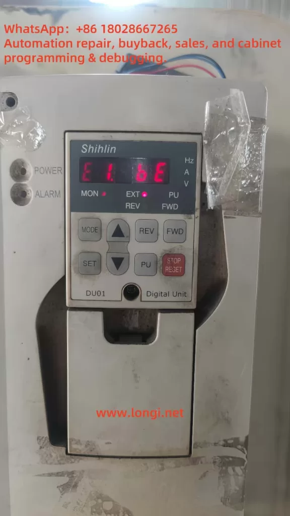
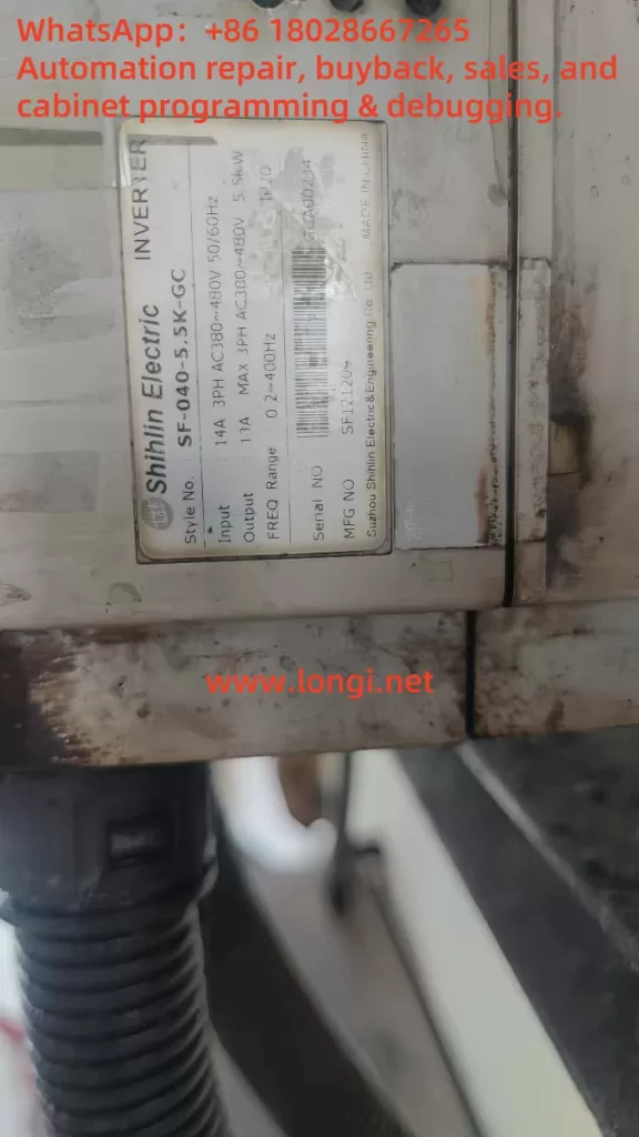
At industrial sites, the Shihlin SF series inverters (e.g., SF‑040‑5.5K) display both “E1” and “BE” (or “bE”) codes simultaneously on the screen, as shown in the figure. This indicates that the inverter is currently in an “E1.BE” alarm state, typically accompanied by internal control shutdown, output disconnection, and other protective actions, causing the driven motor to stop running and affecting production continuity.
2. Alarm Code Interpretation
2.1 Definition of “E1” Abnormality
“E1” is the first-level alarm (Latest Alarm) of the inverter, used for general abnormality alarms. It is triggered immediately when an abnormality occurs in any aspect. However, this code does not directly define the cause of the fault but serves as a “trigger alarm” indicator, requiring subsequent additional information to determine the specific fault.
Through parameter group 06‑5606‑61 (e.g., P.752–P.757), the output frequency, current, voltage, temperature rise, PN voltage, and elapsed operating time at the time of the alarm can be read to assist in diagnosis.
2.2 Meaning of “BE” / “bE” Fault
“BE” refers to Brake‑relay abnormality, one of the hardware detection alarms, indicating an abnormality in the brake relay circuit or an out-of-range detection value.
The relevant code comparison also states: “brake resistor abnormal (Abnormal relay).”
Therefore, “E1.BE” indicates that the inverter has simultaneously triggered an E1 alarm and detected an abnormality in the brake unit.
3. Possible Causes of the Fault
Based on the hardware structure and on-site operating characteristics, the causes can be classified into the following categories:
3.1 Brake Relay Body Fault
The brake relay may have poor contact, damaged moving and stationary contacts, a short-circuited/open-circuited relay coil, etc., preventing it from switching states normally or causing abnormal sensing.
3.2 Brake Module and Resistor Abnormality
If the inverter integrates a braking unit (DBU) but the internal braking resistor is damaged, open-circuited, or loosely connected, it will also result in a failed detection of the brake circuit, triggering a BE alarm.
3.3 Loose Wiring or Interface
The brake unit is connected to the inverter mainboard via pins or terminals. If the connection is loose, oxidized, or dirty, it will also result in the inability to detect the expected state.
3.4 External Circuit Interference
Electromagnetic interference or high-voltage power supplies can cause malfunctions in the brake control circuit, including frequent operation of the brake relay or abnormal feedback. The manual recommends adding magnetic rings for filtering on sensitive lines.
4. Diagnostic Process and Response Strategies
4.1 Safety Isolation and On-Site Initial Inspection
- Power off and shut down the machine, turn off the main power supply, and wait for the DC circuit charge to dissipate (red light goes out).
- Ensure there is no voltage before opening the front door/removing the panel to avoid electric shock.
4.2 Inspection of Wiring, Plugs, and Interfaces
- Disassemble the brake module, clean the interface, and use 600# fine sandpaper or contact cleaner to treat the oxide layer.
- Ensure all connections are tight and reliable, with no increase in impedance.
4.3 Testing of Relay Coil and Moving Contacts
- Use a multimeter to measure the coil resistance to check for open/short circuits.
- Power on and test the coil drive to measure whether it engages. If it fails to engage or the contacts do not close, it is damaged.
4.4 Electromagnetic Interference Investigation
- Check if the brake lines are bundled with high-voltage main circuits or contactor output lines.
- Install magnetic rings or EMI filters and plan the wiring sequence to avoid mutual interference.
4.5 Replacement of Spare Relays or Components
- If a relay is suspected to be damaged, contact the manufacturer to purchase compatible replacement parts. If necessary, send the inverter along with the brake unit for repair.
5. On-Site Maintenance Recommendations
5.1 Regular Inspections
The brake relay should be maintained every 3–6 months, including cleaning the coil, contacts, and checking the wiring harness.
5.2 Environmental Considerations
- Avoid operating the inverter in humid, vibrating, or dusty environments; if necessary, equip the inverter with a protective enclosure and ensure good heat dissipation.
5.3 Parameter Monitoring and Alarm Logging
- Enable parameter groups P.290, P.291, etc., to collect brake action records through the PU panel or PC, enabling earlier detection of abnormal trends.
5.4 Comprehensive Analysis of E1 Abnormalities
“E1,” as a first-level alarm, can be paired with parameter groups P.752–P.758 to obtain on-site condition data. Combined with the alarm code BE, it generally indicates a hardware problem rather than operational parameter issues such as current overload.
6. Case Studies
Case 1: Brake Coil Open Circuit
An inverter on-site displayed an E1.BE alarm. Upon disassembly and inspection, it was found that the brake module had been used for an extended period in a hot environment, causing insulation aging and an open circuit in the internal coil. Replacing the relay module restored normal operation.
Case 2: Connector Oxidation
After multiple power-on cycles, the exposed positions of the relay interface oxidized, resulting in poor contact. Cleaning the contacts, applying anti-oxidation oil, and tightening the connections eliminated the fault.
Case 3: Strong Electrical Interference Triggering False Alarms
The brake output lines were frequently routed in parallel with the main power supply, subject to electromagnetic interference. The factory installed magnetic rings for filtering on the brake lines and rerouted them, after which the BE alarm did not recur.
7. Summary and Recommendations
“E1.BE” represents a brake relay hardware abnormality, not an ordinary PID or current overload fault. Handling should focus on hardware, wiring, and electromagnetic environment investigations. Key points are as follows:
- Ensure safety by powering off before operations.
- Carefully inspect the relay body and coil.
- Clean and tighten all relevant wiring and connectors.
- Strengthen wiring and filtering to prevent EMI.
- Enable alarm logging and monitoring, and conduct regular inspections.
- Replace modules or report to the Shihlin manufacturer for repair if necessary.
By following these methods, on-site equipment can quickly resume stable operation, reducing the risk of mis-shutdowns and production interruptions.
8. Final Recommendations
- Incorporate brake relays and modules into routine maintenance projects.
- Conduct special inspections of on-site wiring specifications and EMI layout.
- Recommend configuring spare parts for commonly used modules at key nodes for quick replacement.
- If BE alarms occur frequently, suspect core hardware aging and directly contact the manufacturer for repair. Do not ignore hardware quality issues.