Introduction
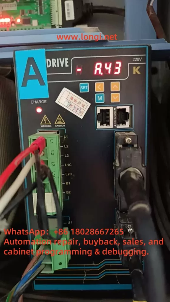
Servo drives are the backbone of precision control in industrial automation, powering applications ranging from CNC machining to robotic assembly lines. The ZSMC K-Series servo drive, renowned for its reliability and efficiency, is no exception. However, even the most robust systems can encounter faults that disrupt operations. One such issue, the A.43 fault, has been reported by a user, with a screenshot showing the fault code displayed on the servo drive. This article delves into the A.43 fault—identified as a “Bus-type encoder cumulative count error”—to provide a comprehensive, step-by-step guide for troubleshooting and resolving it. Drawing from the official user manual (“ZSMC Servo K-Series User Manual Complete Version.pdf,” 2017 Engineering Version V3.0), this guide aims to equip technicians and engineers with the knowledge to address this fault effectively, minimizing downtime and ensuring system reliability.

Understanding the A.43 Fault
The A.43 fault is explicitly defined in the ZSMC K-Series servo drive manual under “Appendix C: Alarm Display List” (Page 191). It is described as “Bus-type encoder cumulative count error.” The accompanying note states, “Encoder cumulative count or encoder motor cumulative circuit connection is damaged.” This fault is classified as a high-priority (H-level) alarm, indicating its potential to significantly impact system performance, yet it is resettable, suggesting that it can often be cleared once the underlying issue is resolved.
At its core, the A.43 fault points to an issue with the bus-type encoder, a critical component that provides feedback on the motor’s position and speed. The “cumulative count” refers to the aggregated position data transmitted over a bus communication protocol (likely RS-485, as hinted in the manual’s communication sections). When this count becomes erroneous—due to hardware failure, wiring issues, or communication disruptions—the servo drive loses its ability to accurately track the motor’s position. This can result in erratic motor behavior, loss of precision, or complete system shutdown, making swift resolution essential.
Possible Causes of the A.43 Fault
To address the A.43 fault, we must first identify its root cause. The manual’s troubleshooting section (Chapter 7, “Fault Diagnosis and Troubleshooting,” Page 135) and practical engineering insights suggest several potential culprits:
- Encoder Hardware Failure
The encoder itself may be faulty due to physical damage, wear from prolonged use, or internal component failure. A damaged encoder can send incorrect or no data, leading to cumulative count errors. - Wiring Issues
Faulty connections between the encoder and the servo drive—such as loose terminals, broken cables, or improper grounding—can interrupt signal transmission, triggering the A.43 fault. - Communication Interference
Since the encoder operates over a bus system, electromagnetic interference (EMI) from nearby equipment (e.g., motors or inverters) or inadequate shielding can corrupt the data, causing count discrepancies. - Power Supply Instability
An unstable or insufficient power supply to the encoder can impair its operation, resulting in erratic count data. The manual hints at power-related considerations in its wiring sections (Chapter 3, Page 17). - Configuration Errors
Incorrect parameter settings in the servo drive, particularly those related to the encoder (e.g., resolution or communication protocol), may lead to misinterpretation of the encoder’s output, as noted in Chapter 5 (Page 54).
Each of these causes requires a distinct approach to diagnosis and resolution, which we will explore in the following sections.
Troubleshooting the A.43 Fault
A systematic troubleshooting process is key to isolating the cause of the A.43 fault. Below is a detailed, step-by-step guide based on the manual and standard servo system practices.
Step 1: Inspect Encoder Wiring
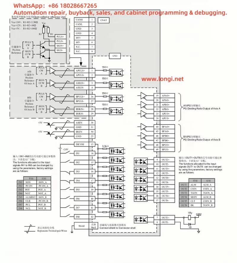
- Action: Refer to Section 3.4, “Encoder Operation Guide Wiring” (Page 27), to verify the encoder cable connections.
- Procedure:
- Check that all connections to the encoder port (e.g., CN1 or CN2) are secure and free of corrosion or damage.
- Ensure the cable shield is properly grounded, as recommended in Section 3.5 (Page 34), to minimize interference.
- Use a multimeter to test the continuity of each wire in the encoder cable, identifying any breaks or shorts.
- Outcome: If wiring issues are found, they must be corrected before proceeding.
Step 2: Test the Encoder Hardware
- Action: Assess the encoder’s functionality, as suggested in Section 7.2, “Servo Drive Maintenance and Inspection” (Page 139).
- Procedure:
- Visually inspect the encoder for physical damage (e.g., cracked housing or burnt components).
- If possible, swap the suspect encoder with a known working unit of the same model to see if the fault persists.
- For advanced diagnostics, use an oscilloscope to monitor the encoder’s output signals, checking for irregularities in the waveform.
- Outcome: A faulty encoder will require replacement.
Step 3: Evaluate Communication Environment
- Action: Investigate potential interference, referencing Section 6.3, “MODBUS Communication Protocol” (Page 107).
- Procedure:
- Ensure the communication cable length complies with RS-485 standards (typically under 1200 meters).
- Identify and mitigate EMI sources near the servo system, such as high-power machinery, by relocating them or adding shielding.
- Verify that the cable routing avoids parallel runs with power lines, as advised in Section 3.8 (Page 36).
- Outcome: Improved shielding or rerouting may resolve communication-related errors.
Step 4: Verify Power Supply Stability
- Action: Check the power supply to the encoder and drive, per Section 3.2, “Typical Main Circuit Wiring Example” (Page 20).
- Procedure:
- Measure the input voltage to the servo drive (typically 220V ±10%) using a multimeter to ensure it’s within spec.
- Monitor the encoder’s power supply voltage (often 5V or 24V) for stability, using an oscilloscope if available to detect fluctuations.
- Outcome: Power instability may necessitate a regulated power source or additional filtering.
Step 5: Review Parameter Settings
- Action: Validate encoder-related parameters, as outlined in Section 5.4.5, “Absolute Encoder Settings” (Page 69).
- Procedure:
- Access the servo drive’s parameter menu via the panel (Section 4.1, Page 38) and check settings like F[009] and F[010], which define encoder data formats.
- Compare these settings against the encoder’s specifications and the manual’s recommendations.
- If uncertain, reset to factory defaults (Section 4.2.6, Page 43) and reconfigure carefully.
- Outcome: Corrected settings should eliminate configuration-induced errors.
Resolving the A.43 Fault
Once the cause is pinpointed, apply the appropriate fix:
- Faulty Encoder: Replace it with a compatible unit, ensuring proper installation per Section 1.2, “Motor Model Naming” (Page 9).
- Wiring Issues: Repair or replace damaged cables, secure connections, and enhance grounding as needed.
- Communication Interference: Install noise filters (Section 4, Page 34), use ferrite cores, or adjust cable paths to reduce EMI.
- Power Supply Problems: Add a voltage stabilizer or filter to ensure consistent power delivery.
- Configuration Errors: Adjust parameters to match the encoder, save changes, and restart the drive.
After resolution, reset the fault via the panel (Section 4.1, Page 38) and test the system under normal operating conditions to confirm the fix.

Preventive Measures
Preventing future A.43 faults requires proactive maintenance and optimization:
- Routine Inspections: Regularly check the encoder, wiring, and connections for wear or damage (Section 7.2, Page 139).
- Environmental Optimization: Maintain an operating environment within 0–40°C and <90% humidity, avoiding EMI sources.
- Parameter Management: Document correct settings and verify them after any system changes.
- Staff Training: Educate operators on proper handling and maintenance to avoid accidental damage.
Conclusion
The A.43 fault in the ZSMC K-Series servo drive, while disruptive, is manageable with a structured approach. By understanding its meaning—a bus-type encoder cumulative count error—and systematically addressing potential causes like hardware failure, wiring issues, or interference, users can restore functionality efficiently. The detailed manual provides a solid foundation for this process, supplemented by practical troubleshooting steps and preventive strategies. With diligent maintenance and adherence to best practices, the reliability of the ZSMC K-Series servo system can be upheld, ensuring seamless performance in demanding industrial applications.
