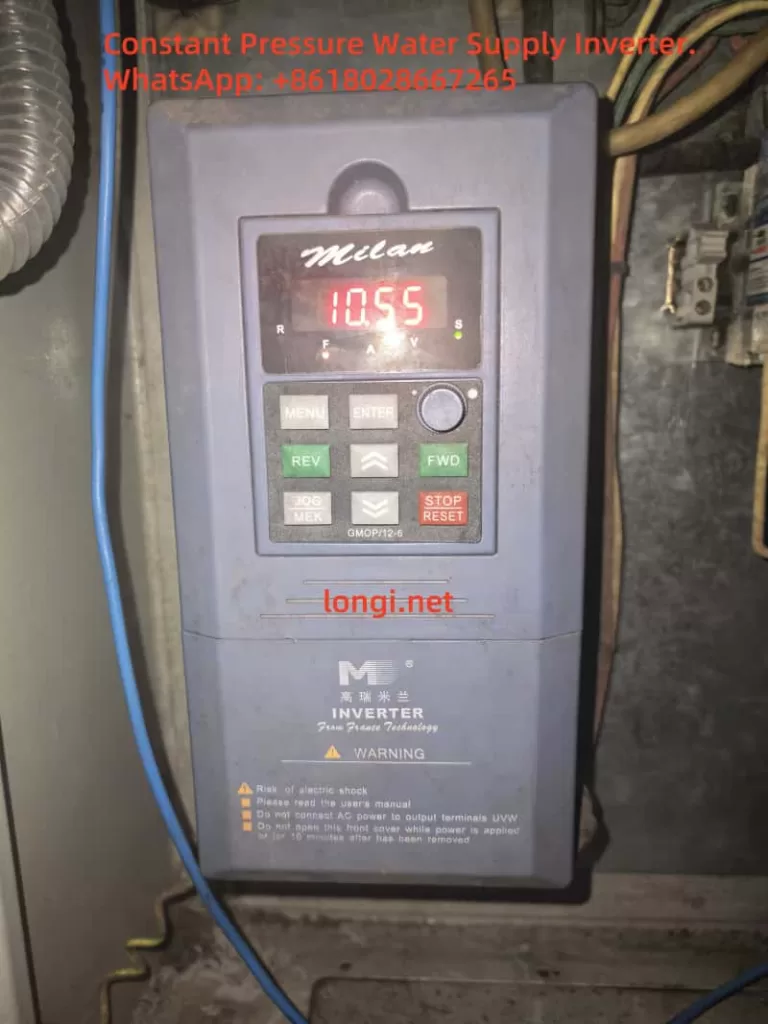
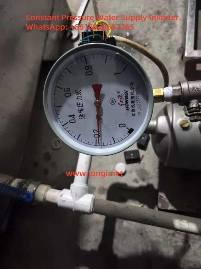
Constant pressure water supply technology is widely used in modern industrial and civil water systems for efficient and energy-saving operation. This project uses the Milan M5000 inverter as the control core, combined with the YTZ-150 potentiometric remote pressure gauge, to construct a closed-loop constant pressure control system. It enables automatic adjustment of a single water pump to ensure the outlet pressure remains stable within the set range.
The system features low cost, easy maintenance, and fast response, making it suitable for small water supply systems, factory cooling water circulation, boiler water replenishment, and more.
2. Main Hardware and Functional Modules
1. Inverter: Milan M5000 Series
Built-in PID controller
Supports multiple analog inputs (0-10V, 0-5V, 4-20mA)
Provides +10V power output terminal for sensor power supply
Rated working voltage ≤6V, but 10VDC tested in practice with stable long-term operation
Outputs a voltage signal (typically 0–5V) varying with pressure via a voltage divider principle
3. Control Objective
Adjust pump speed using the inverter to maintain constant pipe pressure
Increase frequency when pressure drops, and decrease when pressure exceeds the setpoint to save energy
3. Wiring and Jumper Settings
1. 3-Wire Sensor Wiring (Tested with 10V)
Sensor Wire
Function
Inverter Terminal
Red
+10V supply
Connect to +10V
Green
Ground (GND)
Connect to GND
Yellow
Signal output
Connect to VC1 input
2. Analog Input Jumper JP8
Default: 1–2 connected, indicating 0–10V input
Keep the default setting in this project (no need to switch to 2–3)
4. PID Parameter Settings (Based on Field Use)
Parameter
Description
Value
Note
P7.00
Enable closed-loop control
1
Enable PID control
P7.01
Setpoint source
0
Digital input from panel
P7.02
Feedback source
0
VC1 analog input (0–10V)
P7.05
Target pressure value (%)
30.0
Corresponds to 0.3MPa if P7.24=1.000
P7.07
Feedback gain
1.00
Linear scaling factor for feedback
P7.10
PID control structure
1
Proportional + integral control
P7.11
Proportional gain
0.50
Recommended initial value
P7.12
Integral time constant
10.0
In seconds
P7.24
Pressure sensor range (MPa)
1.000
1.000 MPa full-scale
P1.19
Maximum voltage input
5.00
Matched to 0–5V signal range
5. Sleep Function Configuration
To enable energy saving when there is no pressure demand, the inverter can be configured to sleep:
Parameter
Description
Value
Note
P7.19
Wake-up threshold
0.001
Minimum pressure to resume operation (MPa)
P7.20
Sleep threshold
1.000
Enter sleep mode above this value (MPa)
P7.23
Constant pressure mode
1
One-pump control mode
6. PID Tuning Guidelines
After starting the system, observe pressure fluctuations:
If large oscillations, reduce P7.11 (proportional gain)
If sluggish response, reduce P7.12 (integral time)
Aim to maintain output pressure within ±2% of the P7.05 set value
Ensure return pipes have damping to prevent sudden pressure spikes
7. Key Considerations
Keep JP8 jumper at default 1–2 for 0–10V input
YTZ-150 sensor has been tested with 10V power supply and works stably
Ensure proper grounding (PE terminal) to avoid PID interference from common-mode noise
If feedback signal is noisy, add a filter capacitor (0.1–0.47μF) between VC1 and GND
8. Conclusion
With this design, the Milan M5000 inverter combined with the YTZ-150 pressure sensor delivers a cost-effective and reliable constant pressure control solution for water systems. The inverter’s built-in PID control simplifies implementation compared to external PLCs and offers strong performance with minimal tuning. As long as power supply, signal matching, and grounding are properly managed, the system achieves excellent closed-loop control stability.
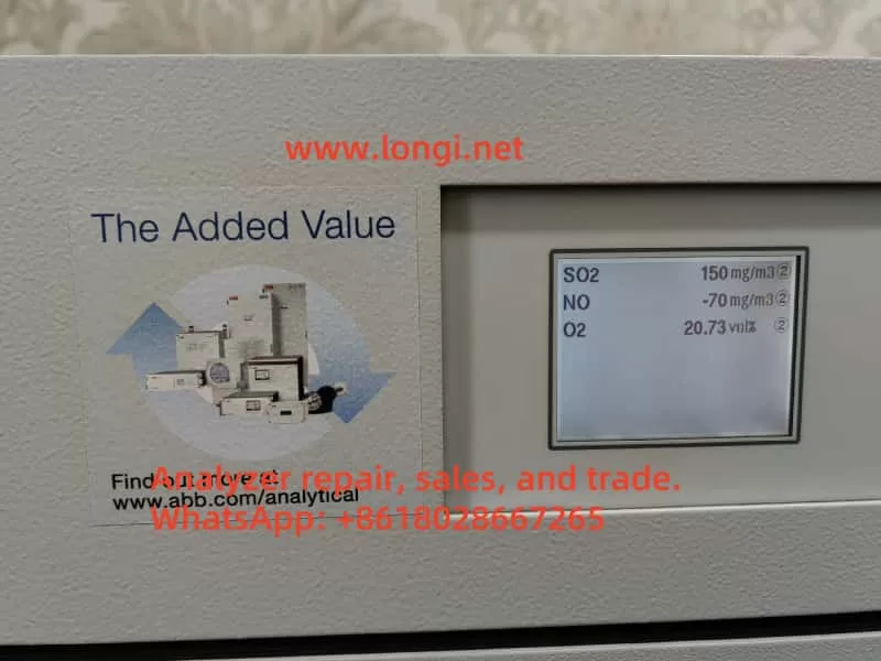
Powerful Functionality: The ABB EL3020 is a high-precision continuous gas analyzer supporting multiple modules (e.g., Uras26, Magnos206) for industrial gas monitoring.
Wide Applications: Primarily used in non-hazardous environments for measuring flammable gases, suitable for industrial process control and environmental monitoring.
Operational Caution: Must be operated by qualified personnel, adhering to strict safety and installation requirements to prevent leaks or equipment damage.
Maintenance and Troubleshooting: Regular calibration and seal integrity checks are critical; fault codes provide clear diagnostics for timely resolution.
User-Friendly Design: Features an intuitive display interface and multiple connectivity options, supporting remote configuration and data logging.
This guide, based on the ABB EL3020 user manual, aims to assist users in understanding its features, usage, precautions, and maintenance procedures.
Features and Capabilities
The ABB EL3020 is a continuous gas analyzer designed for industrial applications, capable of accurately measuring the concentration of individual components in gases or vapors. Part of the ABB EasyLine series, it combines advanced technology with user-friendly design, making it suitable for various industrial settings.
Key Features
Versatile Analyzer Modules: Supports Uras26 (infrared), Magnos206 (oxygen), Caldos27 (thermal conductivity), Limas23 (ultraviolet), and ZO23 (zirconia) modules, enabling measurement of gases like CO, CO₂, CH₄, and O₂.
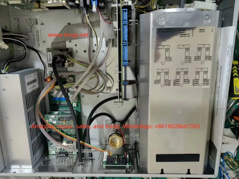
Robust Design: Housed in a 19-inch rack-mounted enclosure with IP20 protection, weighing 7-15 kg, ideal for indoor industrial environments.
Flexible Connectivity: Supports 100-240 V AC power, digital I/O, analog outputs, Modbus, Profibus, and Ethernet interfaces for seamless system integration and remote operation.
Calibration Options: Offers automatic and manual calibration using nitrogen, air, or span gases, configurable via the device or software (e.g., ECT).
Intuitive Interface: Displays gas component names, measured values, and units in measurement mode; menu mode provides configuration and maintenance functions with password protection and a 5-minute timeout.
Data Communication: Connects to computers via Ethernet using TCT-light and ECT software for configuration, calibration, and data logging, supporting Modbus TCP/IP protocol.
Applications and Usage Precautions
Applications
The ABB EL3020 is designed for measuring flammable gases in non-hazardous environments, with applications including:
Industrial Process Control: Monitors gas concentrations in production processes to ensure stability.
Environmental Monitoring: Measures industrial emissions to comply with regulatory standards.
Energy Sector: Used in power plants for gas analysis to enhance efficiency and safety.
Chemical Industry: Monitors gas components in chemical reactions to ensure safety and quality.
The device is suitable for indoor environments below 2000 meters altitude, with flammable gas concentrations not exceeding 15 vol.% CH₄ or C1 equivalents. It is not suitable for ignitable gas/air or gas/oxygen mixtures or corrosive gases without proper preprocessing.
Usage Precautions
To ensure safety and performance, adhere to the following precautions:
Personnel Requirements: Only qualified personnel familiar with similar equipment should operate or maintain the device.
Safety Compliance: Follow national electrical and gas-handling safety regulations, ensure proper grounding, and avoid using damaged or transport-stressed equipment.
Installation Environment: Install in a stable, well-ventilated location away from extreme temperatures, dust, and vibrations. For flammable gas measurements, ensure adequate air circulation (minimum 3 cm clearance), and if installed in a closed cabinet, provide at least one air change per hour.
Gas Handling: Use stainless steel or PTFE gas lines, avoid opening combustion gas paths, and regularly check seal integrity to prevent leaks that could cause fires or explosions. Limit combustion gas flow (e.g., max 10 l/h H₂ or 25 l/h H₂/He mixture) and install a shut-off valve in the gas supply line.
Environmental Protection: Protect the device from mechanical damage or UV radiation, especially the display window.
Usage Restrictions: The oxygen sensor and integrated gas feed option must not be used for flammable gas measurements.
Detailed Usage Steps and Methods
Preparation
Before installing the EL3020, ensure:
Thorough review of the manual to understand application and safety requirements.
Preparation of necessary materials, such as gas lines, fittings, and power cables.
Verification that the installation site meets environmental requirements (stable, ventilated, no extreme temperatures).
Unpacking and Installation
Unpacking: Due to the device’s weight (7-15 kg), two people are recommended for unpacking.
Gas Connections: Use PTFE sealing tape to connect sample, process, and test gas lines, ensuring a tight seal.
Installation: Secure the 19-inch enclosure in a cabinet or rack using appropriate mounting rails.
Connections
Gas Lines: Connect sample, process, and test gas lines, ensuring cleanliness and secure sealing. Install a micro-porous filter and flowmeter for protection if needed.
Electrical Connections: Connect power (100-240 V AC), digital I/O, analog outputs, and communication interfaces (Modbus, Profibus, Ethernet) as per the manual’s wiring diagrams.
Startup
Power On: Connect and turn on the power supply.
Purging: Purge the sample gas path with an inert gas (e.g., nitrogen) for at least 20 seconds (100 l/h) or 1 hour (200 l/h) to clear residual gases.
Warm-Up: Allow 0.5-2 hours for warm-up, depending on the analyzer module.
Introduce Sample Gas: After warm-up, introduce the sample gas.
Configuration and Calibration: Verify configuration settings and perform calibration if necessary, using test gases (e.g., nitrogen) to adjust zero and span points.
Operation
Measurement Mode: The display shows gas component names, measured values, and units for routine monitoring.
Menu Mode: Access configuration, calibration, or maintenance functions via the menu, requiring a password. The system auto-exits after 5 minutes of inactivity.
Calibration Methods: Perform automatic calibration (using preset test gases) or manual calibration (via menu or ECT software to adjust setpoints).
Data Logging: Use TCT-light or ECT software via Ethernet for data recording, compliant with QAL3 requirements.
Remote Monitoring: Integrate with monitoring systems via Modbus TCP/IP protocol.
Routine Maintenance and Fault Code Meanings
Routine Maintenance
To ensure long-term performance, conduct regular maintenance:
Seal Integrity Checks: Use pressure tests or leak detectors to regularly verify the integrity of sample and combustion gas paths, ensuring a leak rate < 1×10⁻⁴ hPa l/s for combustion gas and < 2×10⁻⁴ hPa l/s for sample gas.
Calibration: Perform automatic or manual calibration as needed, using specific test gases (e.g., nitrogen) to adjust setpoints and ensure measurement accuracy.
Visual Inspection: Regularly check for wear, damage, or contamination, particularly in gas lines, fittings, and the display.
Software Updates: Periodically update ECT and other software to ensure compatibility and functionality.
Fault Codes
The EL3020 provides status messages (codes 110 to 803), categorized as follows:
A: Failure
W: Maintenance Request
F: Maintenance Mode
S: Overall Status
Common fault codes and their handling methods are listed below:
Code
Category
Meaning
Handling Method
110
A S a
Instrument is booting
No action required, informational
122
A S a
IO module defective
Replace IO module
250
A S a
Analyzer not found
Check connectors and cables
301
A S a
Measured value exceeds A/D converter range
Check sample gas concentration and connectors, contact service if needed
322
A S a
Flame is out
Check gas supply and heater plug (for flame-based modules)
412
F S a
Ignition failed
Manually restart via menu, check process gases
Maintenance Procedures
Identify Fault: Access fault codes via the menu.
Troubleshooting: Follow the manual’s instructions for each fault code. For example:
Code 322 (Flame Out): Check combustion gas supply and heater plug.
Code 250 (Analyzer Not Found): Inspect cables and connectors.
Contact Service: If the issue persists, contact ABB Service; avoid attempting repairs beyond your qualifications.
Conclusion
The ABB EL3020 Continuous Gas Analyzer is a robust and versatile tool for industrial gas monitoring, offering high precision and flexibility across various applications. By following the usage steps, precautions, and maintenance procedures outlined in this guide, users can ensure safe operation and sustained performance. Regular calibration, seal integrity checks, and prompt resolution of fault codes are essential for maintaining measurement accuracy and safety.