1. Application Background and Industry Pain Points
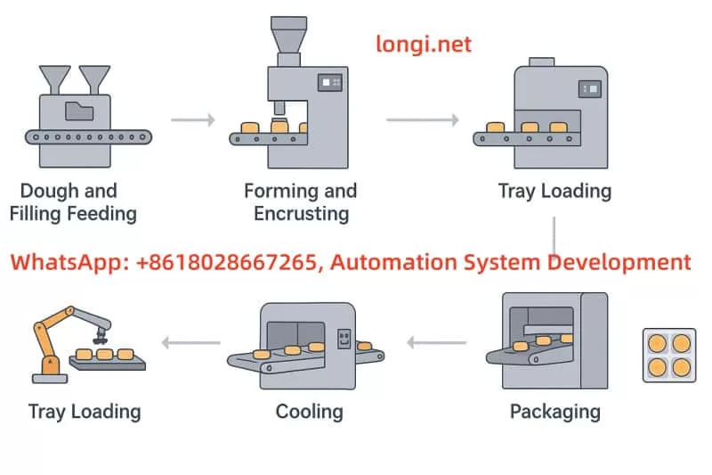
In enclosed or semi-enclosed environments such as underground parking lots, automobile repair workshops, welding workshops, paint booths, and other industrial sites, harmful gases like carbon monoxide (CO), emitted from vehicle exhaust, fuel combustion, or industrial processes, can accumulate over time. This presents a health risk to workers and affects the quality of air. Therefore, an intelligent, automated ventilation control system is needed to monitor and regulate air circulation in real time.
Traditional ventilation systems mostly run at fixed speeds, which are simple but result in high energy consumption, low efficiency, and slow response to fluctuating CO concentrations. To address these issues, this solution designs an intelligent ventilation system based on Longi 900 Series Variable Frequency Drives (VFD) and RKC PID controllers for automatically adjusting fan speed using PID closed-loop control, ensuring good air quality in a variety of settings.
2. System Components and Working Principles
1. Key Components
| Module Category | Product Selection | Function Description |
|---|---|---|
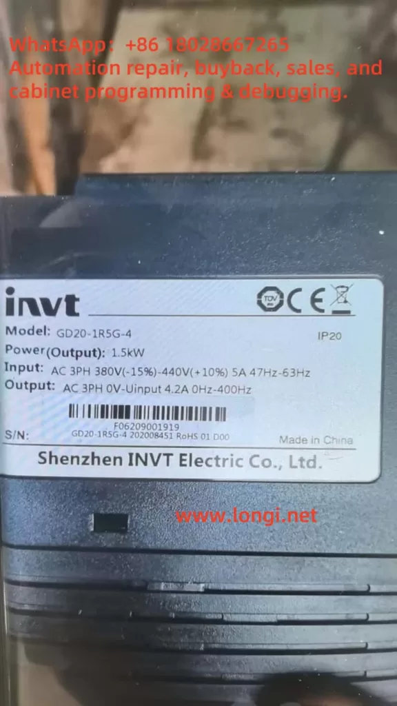
| VFD (Variable Frequency Drive) | Longi 900 Series VFD | Controls fan speed, adjusts airflow rate automatically |
| PID Controller | RKC CH102 or REX-C100 | Receives CO sensor input and outputs control signals (4-20mA) |
| Carbon Monoxide Sensor | ZE25-CO (Winsen) | Detects CO concentration in real time, outputs analog signals |
| Ventilation Equipment | Centrifugal Fan or Duct Fan | Regulates exhaust air according to VFD adjustments |
| Control Panel | Custom-made | Displays status, allows manual/automatic switch |
2. Control Logic and Operation Principles
(1) CO Concentration Detection
The CO sensor (e.g., Winsen ZE25-CO) continuously monitors the CO concentration in the air, typically outputting a 4-20mA analog signal. When the concentration exceeds a set threshold, it triggers subsequent control actions.
(2) PID Controller Adjustment
The RKC PID Controller compares the actual CO concentration with the set target concentration (e.g., 30ppm) and calculates the required adjustment signal using proportional-integral-derivative (PID) logic. It then outputs a control signal (4-20mA).
(3) VFD Speed Regulation
The Longi 900 Series VFD receives the analog control signal from the PID controller and adjusts the fan motor speed accordingly. For example, if the CO concentration is high, the PID controller will instruct the VFD to increase the speed, thereby increasing the airflow for faster exhaust.
(4) Feedback and Protection
The system continuously monitors CO concentration, and when it exceeds a safe level, the fan speed is increased automatically. Once the concentration drops back to a safe level, the fan speed is reduced to the minimum. This process optimizes energy use while ensuring the safety of workers.
3. Longi 900 Series VFD Advantages
| Feature | Description |
|---|---|
| PID Control Support | Built-in PID control parameters for automatic regulation based on external input |
| Flexible Analog Input Interfaces | Supports 0-10V, 4-20mA, and other input signals, adaptable to various control needs |
| High Reliability | Multiple protection features including overload, overvoltage, and overheat safeguards |
| Energy Efficiency | Wide speed regulation range (0-500Hz), enabling precise fan speed adjustments to reduce energy consumption |
| Ease of Maintenance | User-friendly interface, easy to maintain, and extend device lifespan |
4. Suggested System Configuration
| Name | Model | Quantity | Description |
|---|---|---|---|
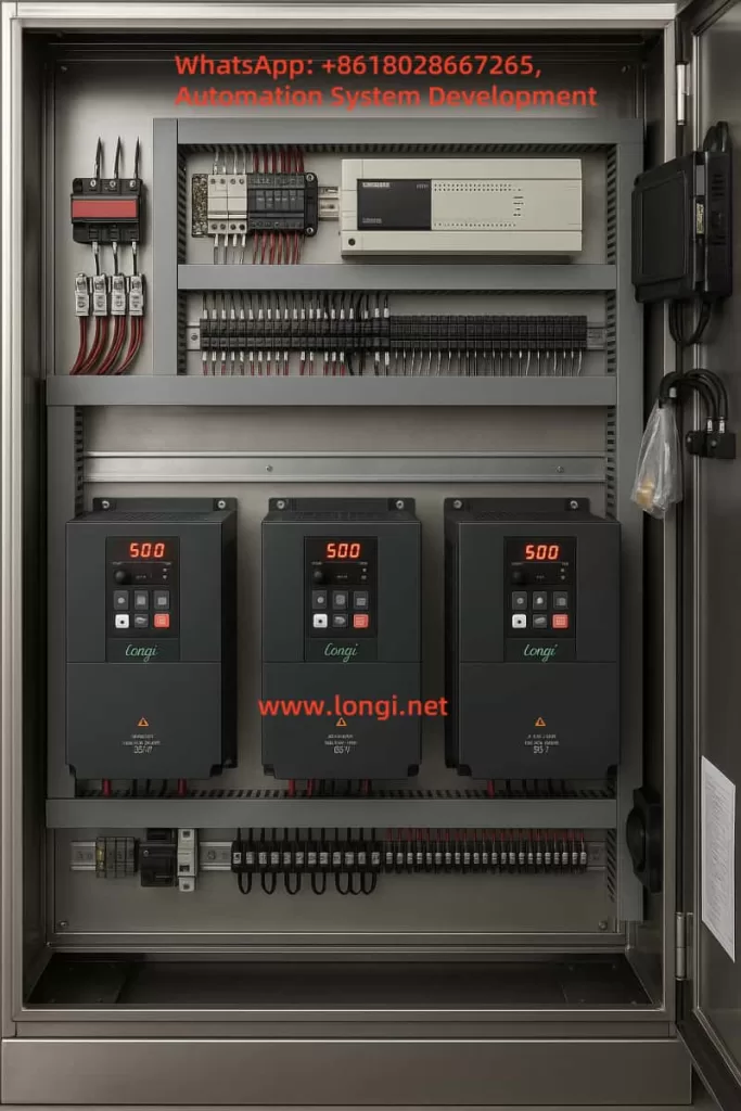
| VFD | Longi 900 Series 900-0015G3 (1.5kW) | 1 unit | Drives the fan, adjusts speed according to PID control signals |
| PID Controller | RKC CH102 | 1 unit | Receives CO sensor signal, outputs control signal (4-20mA) |
| CO Sensor | Winsen ZE25-CO | 1 unit | Detects CO concentration, outputs analog signal |
| Fan and Motor | YVF2 1.5kW + Centrifugal Fan | 1 set | Core of the system, performs exhaust tasks |
| Control Panel | Custom-made | 1 unit | Includes operation buttons, display indicators, emergency stop |
Suggested Parameter Settings
For Longi 900 Series VFD, the following parameters are recommended:
| Parameter | Description | Suggested Value |
|---|---|---|
| F0-00 | Command Source | 1 (External Terminal Control) |
| F0-01 | Main Frequency Source | 2 (AI1) |
| F5-02 | PID Feedback Source | 1 (Analog Input) |
| F5-08 | Sensor Type | 1 (4-20mA) |
| F5-01 | PID Setpoint | 30ppm (Reference Value) |
| F0-04/05 | Acceleration/Deceleration Time | 5-10s |
5. System Deployment and Maintenance Recommendations
1. Installation and Layout
- Sensor Installation: CO sensors should be installed in central locations or at the end of exhaust ducts, approximately 1.5-2 meters above the floor, to ensure complete area monitoring.
- PID Controller: Should be installed in a location visible to the operator for easy adjustment of parameters.
- VFD and Fan Installation: VFD should be installed in an electrical control cabinet with adequate ventilation, avoiding high temperatures and humidity.
2. System Debugging and Operation
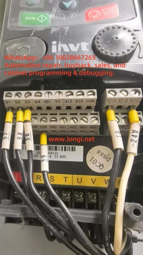
- Before powering up, verify that the wiring is correct, especially ensuring that the VFD output terminals (U/V/W) are not connected to the mains.
- Set the RKC PID Controller:
- Setpoint (SV) to 30ppm.
- Control mode to PID, output signal set to 4-20mA.
- After connecting the CO sensor, adjust PID parameters (proportional, integral, and derivative gains) for optimal system response.
3. Maintenance and Upkeep
| Equipment | Maintenance Task | Frequency |
|---|---|---|
| CO Sensor | Zero-point calibration and functionality check | Every 6 months |
| PID Controller | Output signal and display check | Every 12 months |
| VFD | Heat sink cleaning and electrical check | Every 12-18 months |
| Fan Motor | Lubrication and current measurement | Every 3-6 months |
6. System Upgrades and Expansion Recommendations
1. Remote Communication Module
The Longi 900 Series VFD supports Modbus RTU communication. Add a remote communication module for cloud-based monitoring, data logging, and alarm notifications, enabling more advanced smart management.
2. Multi-Region Control
For large workshops or parking lots, deploy multiple independent ventilation units, each with its own CO sensor, to control fan speeds regionally, optimizing energy use.
3. Integration of Particulate Matter (PM2.5/PM10) Sensors
Expand the system to monitor and control particulate pollution, ensuring air quality across various industrial processes.
4. Lighting System Integration
Incorporate lighting control, turning on both the lights and the ventilation system when personnel enter a room, and turning them off after a delay once they exit, further reducing energy consumption.
7. Conclusion and Value Proposition
With the Longi 900 Series VFD, RKC PID Controllers, and CO Sensor Integration, this system enables automatic fan speed adjustment to ensure air quality and worker safety. By utilizing energy-efficient, smart control, this solution meets the needs of environments like workshops, parking garages, and industrial sites, and provides significant benefits in terms of energy savings, safety, and environmental health.
This system is an ideal solution for maintaining high standards of air quality while optimizing energy use in industrial facilities.