1. Introduction
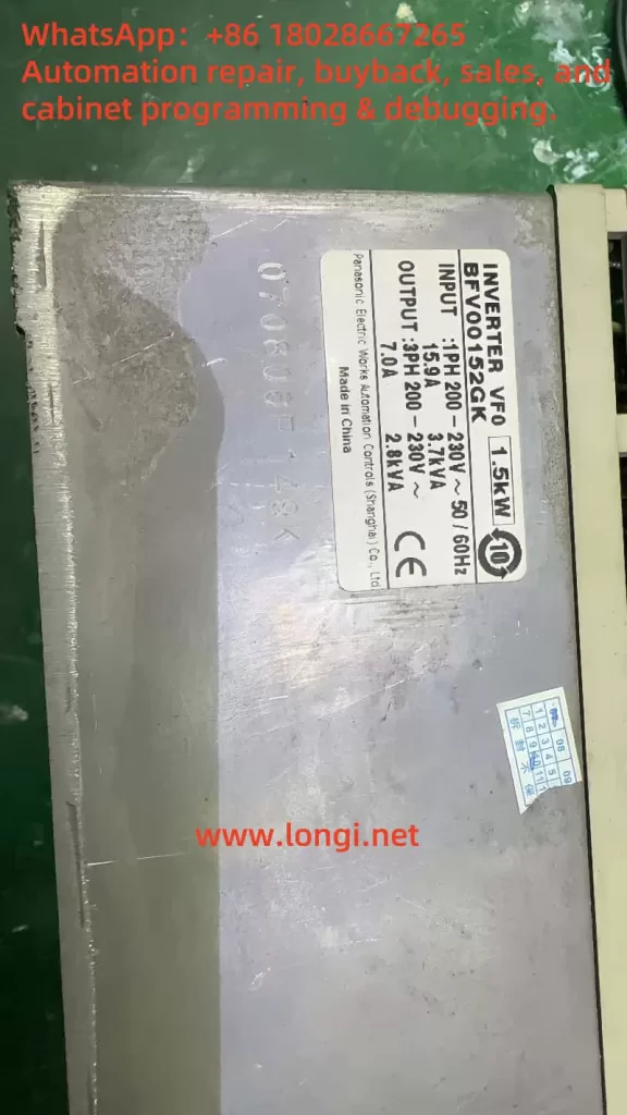
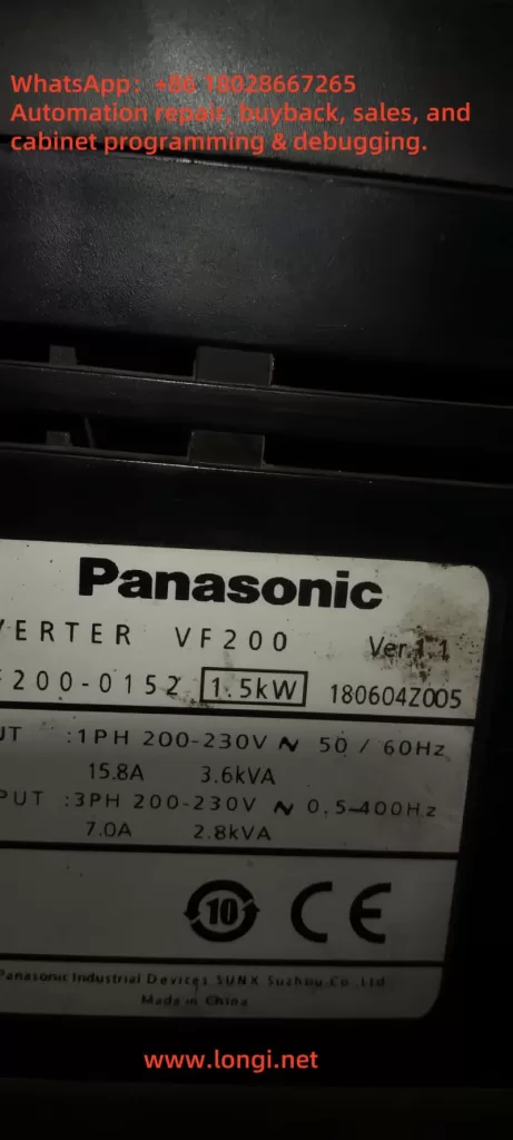
The Panasonic VF200 series inverter is a widely used device in industrial automation, known for its efficiency, reliability, and versatility. This series supports single-phase 200V (0.2kW to 2.2kW) and three-phase 400V (0.75kW to 15kW) power supplies, making it suitable for various motor control applications. However, users may encounter issues during operation, one of the most common and troubling being the “CPU” fault code displayed on the inverter’s screen accompanied by the ALARM light. This fault indicates an abnormality in the inverter’s core control system, potentially causing the device to stop functioning and disrupting production efficiency. This article will provide a detailed analysis of the “CPU” fault, its possible causes, and a systematic approach to troubleshooting and resolving the issue to help users quickly restore normal operation.
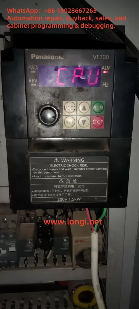
2. Meaning of the “CPU” Fault
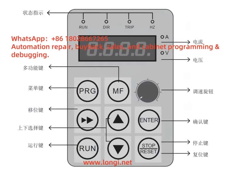
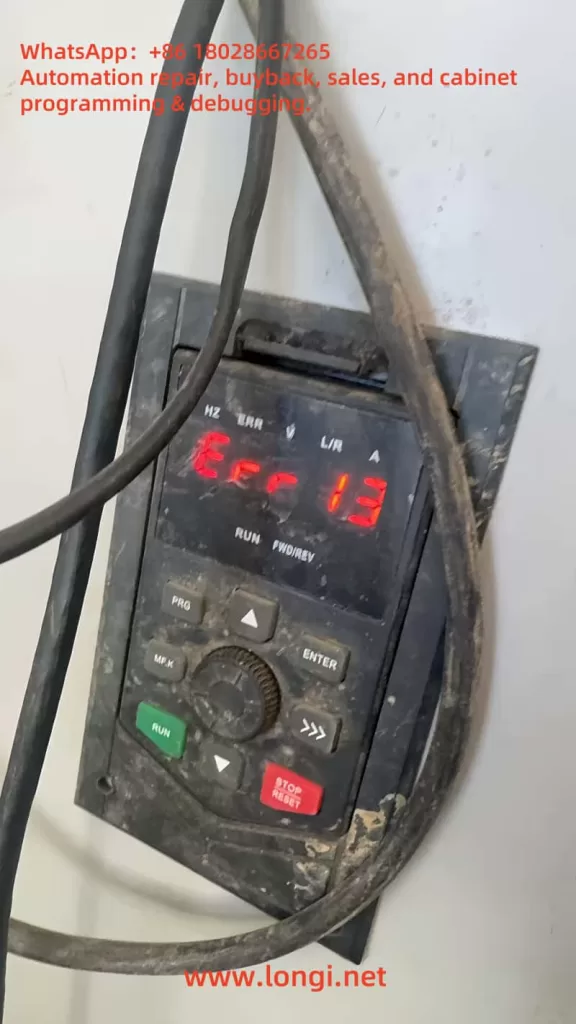
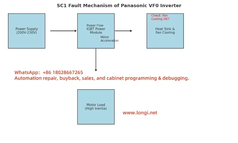
In the Panasonic VF200 series inverter, when the display shows the “CPU” fault code and the ALARM light is on, it typically indicates a problem with the inverter’s Central Processing Unit (CPU). The CPU is the “brain” of the inverter, responsible for executing control algorithms, processing input and output signals, and coordinating the overall operation of the device. When the CPU detects an abnormality in itself or related systems, the inverter enters protection mode, stops operation, and alerts the user by displaying the “CPU” code and lighting the ALARM lamp.
According to the VF200 series user manual and technical documentation, the “CPU” fault may be associated with other anomalies such as instantaneous overcurrent (OC1-3) or temperature abnormalities (OH). This suggests that the “CPU” error may not solely be a hardware issue with the CPU but could also be triggered indirectly by external conditions or system operational states. Therefore, understanding the potential causes of this fault is crucial.
3. Possible Causes of the “CPU” Fault
The occurrence of the “CPU” fault can be triggered by various factors. Below are detailed analyses of several common causes:
1. Power Supply Issues
- Voltage Instability: The VF200 series inverter has strict requirements for input power. If the power supply voltage exceeds the rated range (single-phase 200V or three-phase 400V) or fluctuates, it may lead to insufficient power or overvoltage damage to the CPU.
- Power Interference: Surges or electromagnetic interference (EMI) in the power supply can disrupt the normal operation of the CPU, especially in industrial environments with poor power quality.
2. Overheating Issues
- Temperature Abnormality (OH): If the internal temperature of the inverter is too high, it may be due to poor ventilation, high ambient temperature, or a malfunctioning cooling fan (FAn). High temperatures can affect the stability of the CPU and even trigger faults.
- Overloading: Operating under high load conditions for extended periods can lead to inadequate heat dissipation, further exacerbating temperature increases.
3. Overcurrent Issues
- Instantaneous Overcurrent (OC1-3): Motor failures, sudden load changes, or wiring errors can cause the current to exceed the inverter’s rated value. This situation may place excessive stress on the CPU, triggering the protection mechanism and displaying the “CPU” error.
- Improper Parameter Settings: If the current limit parameters are set incorrectly, it may fail to effectively prevent overcurrent conditions.
4. Firmware or Software Issues
- Firmware Corruption: Firmware is the software foundation for CPU operation. If the firmware is corrupted during an update or due to electrical interference, the CPU may not function properly.
- Parameter Errors: Parameters set by the user that do not match the actual application may cause the CPU to execute abnormal instructions.
5. Hardware Failures
- CPU or Control Board Damage: Long-term use, manufacturing defects, or physical damage can lead to hardware failures in the CPU or its control board, such as circuit board burnout or component aging.
- Connection Issues: Loose or poor internal connections may disrupt data communication between the CPU and other modules.
6. External Interference
- Electromagnetic Interference: High-power equipment commonly found in industrial environments can generate strong electromagnetic interference, affecting the CPU’s signal processing capabilities.
- Poor Grounding: High grounding resistance can lead to the accumulation of electrical noise, interfering with CPU operation.
4. Steps to Troubleshoot and Resolve the “CPU” Fault
To effectively resolve the “CPU” fault, users should follow these systematic steps for troubleshooting and resolution:
1. Initial Checks and Safety Preparations
- Power Off: According to the warning labels on the inverter, disconnect the power and wait at least 5 minutes to ensure the internal capacitors are discharged, avoiding the risk of electric shock.
- Record Status: Note the operating conditions when the “CPU” fault occurred (such as load, ambient temperature, etc.) to provide clues for subsequent diagnosis.
2. Check Power Supply Conditions
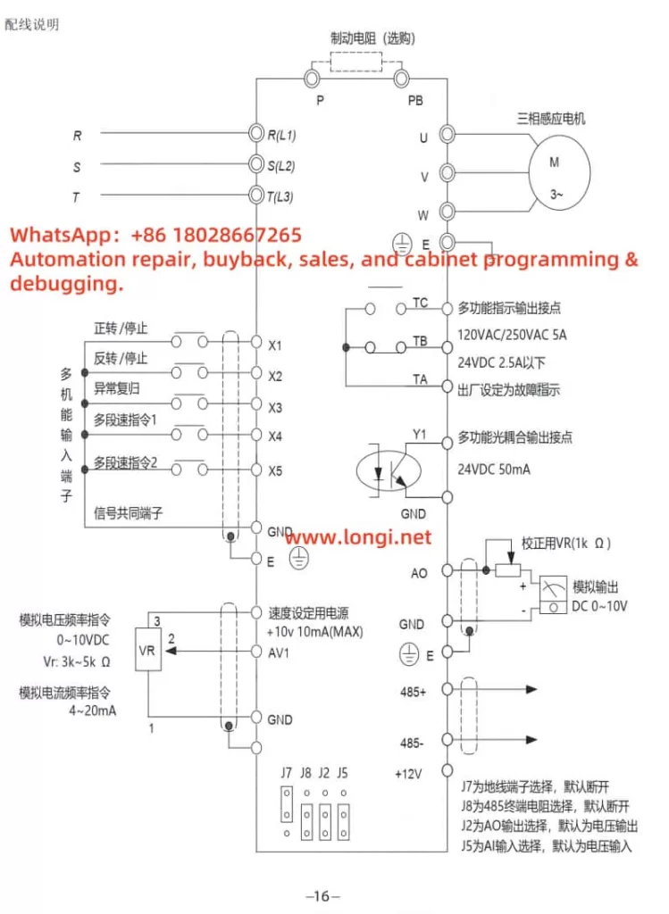
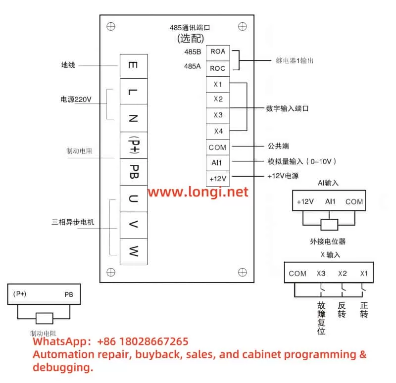
- Measure Voltage: Use a multimeter to measure the input power voltage, ensuring it is within the rated range for single-phase 200V (0.2kW to 2.2kW) or three-phase 400V (0.75kW to 15kW) and free from significant fluctuations.
- Check Grounding: Confirm that the grounding resistance is less than 10 ohms to eliminate interference caused by poor grounding.
3. Check for Overheating Issues
- Ambient Temperature: Ensure the operating environment temperature is between 0°C and 40°C, and check if the ventilation openings are blocked.
- Cooling Fan: Verify if the fan is operating normally; replace it if faulty.
- Clean the Device: Use compressed air to remove dust from inside the inverter to ensure proper heat dissipation.
4. Check for Overcurrent Issues
- Load Check: Ensure the motor load does not exceed the inverter’s rated capacity and check for motor short circuits or mechanical jams.
- Wiring Check: Inspect the wiring between the inverter and the motor to ensure it is correct and secure.
- Parameter Adjustment: Use the “MODE,” “SET,” “UP,” and “DOWN” keys to access parameter settings and check the current limit parameters, ensuring they are within 1% to 200% of the rated output current.
5. Reset and Firmware Check
- Power Reset: After powering off and waiting 5 minutes, power on again to see if the “CPU” error disappears.
- Restore Factory Settings: If the issue persists, follow the user manual to restore factory settings and then reconfigure necessary parameters.
- Firmware Update: Contact technical support to obtain the latest firmware and follow the instructions to update it.
6. Hardware Inspection
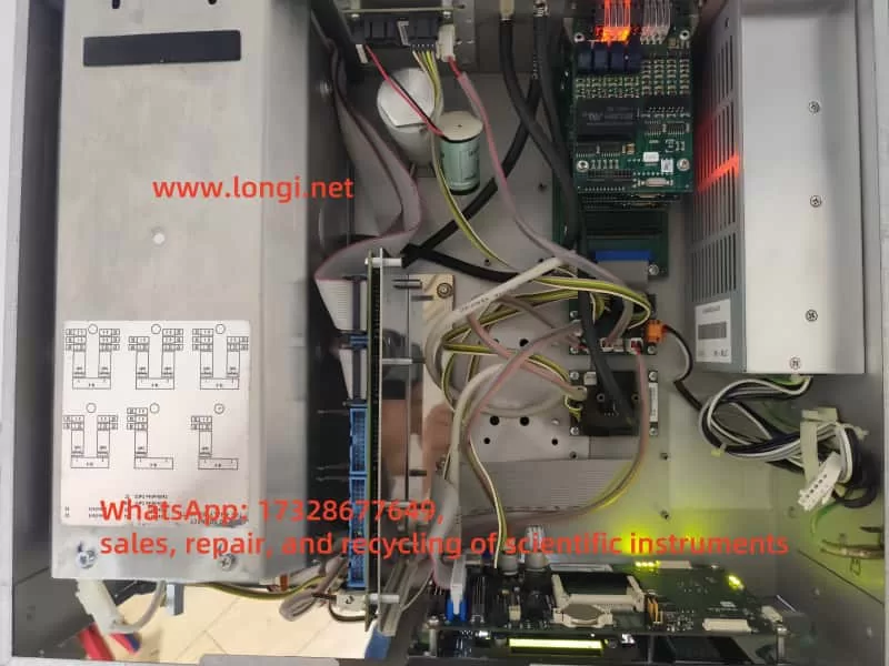
- Visual Inspection: Open the inverter casing and check the control board for signs of burning, odors, or damaged components.
- Connection Repair: If loose connections are found, secure them with insulating tape and re-tighten.
- Component Replacement: If hardware damage is severe, contact Panasonic after-sales service to replace the original control board.
7. Reduce External Interference
- Isolate Interference Sources: Separate the inverter from high-power equipment or install shielding covers.
- Use Shielded Cables: Ensure that control signal lines and power lines use shielded cables to reduce electromagnetic interference.
8. Testing and Verification
- Operation Test: After completing the above steps, restart the inverter and observe if the “CPU” error is resolved.
- Diagnostic Function: Use the inverter’s error log function to check for other related fault codes (such as OC1-3, OH, etc.).
9. Seek Professional Support
- If the issue remains unresolved, contact Panasonic technical support, providing detailed fault information, model (VF200), and troubleshooting records for remote diagnosis or on-site repair.
5. Preventive Measures for “CPU” Faults
To prevent the recurrence of “CPU” faults, users can take the following preventive measures:
- Regular Maintenance
- Clean dust every 6 months, check wiring and fan status to ensure proper heat dissipation and electrical connections.
- Power Optimization
- Install voltage stabilizers or UPS to ensure stable power supply and avoid voltage spikes.
- Environmental Management
- Keep the operating environment clean, dry, and avoid high temperatures and humidity, ensuring good ventilation.
- Firmware Management
- Regularly check firmware versions, back up parameters before updating to ensure software stability.
- Standardized Operation
- Train operators to set parameters correctly according to the user manual to avoid malfunctions caused by incorrect operations.
6. Conclusion
The “CPU” fault displayed on the Panasonic VF200 series inverter, accompanied by the ALARM light, is a serious issue that requires prompt attention. It can be caused by power instability, overheating, overcurrent, firmware issues, hardware failures, or external interference. By following the systematic troubleshooting steps provided in this article, users can start with checking power and environmental conditions, then delve into hardware and firmware aspects to identify the root cause and apply targeted solutions. Additionally, regular maintenance and optimizing the operating environment are key to preventing faults. If self-troubleshooting fails, contacting Panasonic’s official support is advisable. Through these methods, users can not only resolve the current “CPU” fault but also enhance the long-term stability and lifespan of the equipment, ensuring reliable support for industrial production.