
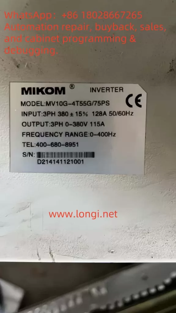
The MIKOM MV series inverter is a crucial device in the field of industrial automation, and its user manual elaborates on key aspects such as equipment operation, parameter settings, and troubleshooting. This article provides systematic guidance on four core modules: operation panel functions, parameter settings, external control, and fault handling, based on the content of the manual.
1. Operation Panel Function Analysis
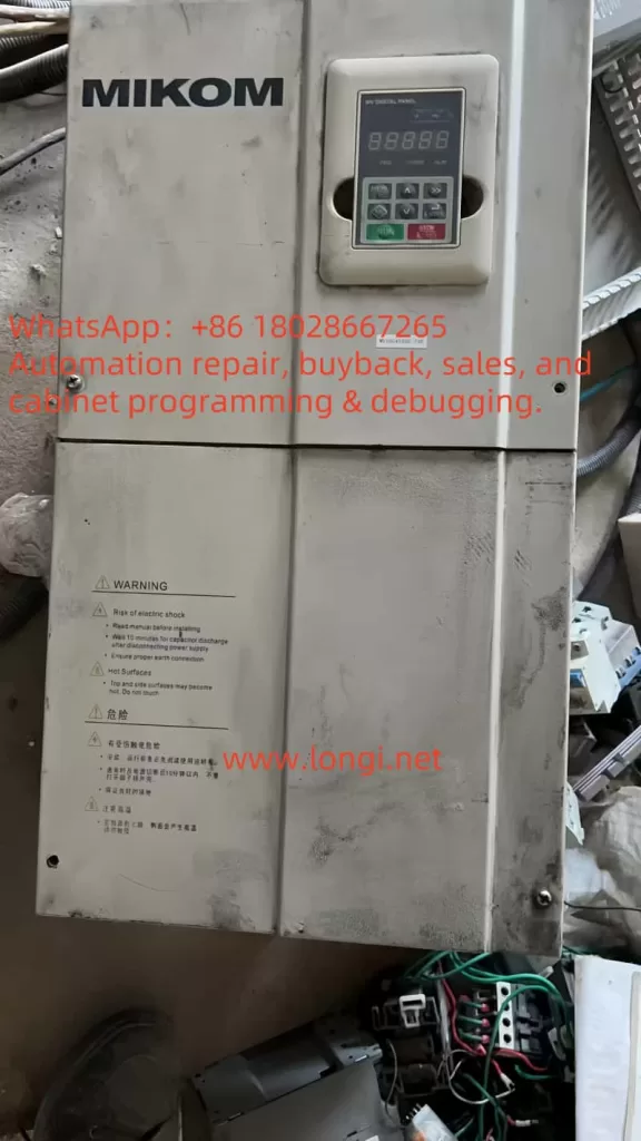
The operation panel is the direct interface for users to interact with the inverter, designed with both functionality and ease of use in mind. The panel’s main components include an LED display, function keys, and status indicators. The LED display shows real-time operating parameters such as output frequency, current, and voltage, and indicates operational status (e.g., RUN/STOP) and fault codes (e.g., Er.XX) through symbols. The function keys are clearly arranged, including:
- MENU/ESC Key: Used to enter the parameter settings menu or exit the current operation interface.
- ENTER Key: Confirms parameter modifications or enters submenus.
- RUN/STOP Key: Controls the inverter’s start and stop; pressing and holding it initiates emergency stop.
- MK Key: A multifunctional key whose function is defined by parameter P50.03 (e.g., inching control, free stop).
- Increment/Decrement Keys (>, <): Adjust parameter values or switch display pages.
- Shift Key (>>): Selects operation bits during parameter modification or cycles through display interfaces.
By using these keys in combination, users can perform operations such as parameter browsing, modification, and device control. For example, pressing and holding the MENU key for 3 seconds enters the password verification interface, where entering the correct password grants access to protected parameters.
2. Parameter Settings and Security Protection
1. Restoring Factory Default Parameters
To restore the device to its initial state, you can select the restoration range through parameter P50.20:
- P50.20=0: Restores basic menu parameters (P00-P19 groups).
- P50.20=1: Restores advanced menu parameters (P20-P49 groups).
- P50.20=2: Restores user-defined menu parameters (P50-P99 groups).
Operation steps: Enter the menu → select P50.20 → press ENTER to confirm → use the increment/decrement keys to choose the restoration range → press ENTER again to execute.
2. Password Setting and Removal
To prevent accidental operations, a user password can be set via parameter P50.00:
- Setting the password: Enter P50.00 → input a 4-digit password → press ENTER to confirm → the password takes effect after 1 minute of inactivity.
- Password verification: The system prompts for password entry when modifying protected parameters.
- Password removal: Power cycle the device or enter the correct password and press ENTER to lift protection.
3. Parameter Access Restrictions
Three levels of protection can be set via parameter P50.02:
- P50.02=0: No protection; all parameters can be modified.
- P50.02=1: Partial parameters locked (e.g., P00 group basic parameters are accessible, P20 group advanced parameters are locked).
- P50.02=2: All parameters locked; modifications require a password.
Additionally, the thousand’s place of parameter P50.03 can lock operation panel keys (e.g., disabling RUN/STOP operations), further enhancing security.
3. External Control Function Implementation
1. External Terminal Forward/Reverse Control
Configure terminal functions via parameter P10 group:
- Forward control: Set P10.01=1 (DI1 terminal as forward command).
- Reverse control: Set P10.02=2 (DI2 terminal as reverse command).
- Combined logic: Set multi-terminal combined logic via P10.03-P10.06 (e.g., DI1+DI3 for forward inching).
Wiring example: Connect the forward button to the DI1 terminal and COM terminal, and the reverse button to the DI2 terminal and COM terminal.
2. External Potentiometer Frequency Adjustment
Implementation steps:
- Parameter settings: Enter the P12 group → set P12.01=1 (AI1 as frequency reference source) → P12.03=0 (0-10V corresponds to 0-50Hz).
- Hardware wiring: Connect an external potentiometer (10kΩ) to AI1 (terminal 10) and GND (terminal 11).
- Debugging tips: Rotate the potentiometer and observe if the frequency value displayed on the LED changes linearly. Adjust P12.04 (filter time) if fluctuations occur.
4. Fault Codes and Handling Procedures
The manual lists over 20 fault codes and solutions. Below is a guide to common fault handling:
| Fault Code | Fault Description | Possible Causes | Handling Steps |
|---|---|---|---|
| Er.01 | Acceleration overcurrent | Sudden load change, short acceleration time | Extend acceleration time (P01.01), check load |
| Er.02 | Deceleration overcurrent | Braking resistor failure, short deceleration time | Check braking unit, extend deceleration time (P01.02) |
| Er.07 | Input phase loss | Poor power line contact | Check input voltage and wiring |
| Er.11 | Motor overload | Excessive load, motor fault | Reduce load, check motor insulation |
| Er.15 | Communication fault | Loose communication cable, protocol mismatch | Check wiring, verify communication parameters (P30 group) |
Fault troubleshooting process:
- Record the fault code (displayed on the LED or query historical records via P34 group).
- Identify the cause using the fault list in the manual.
- Follow the recommended steps (e.g., check power supply, adjust parameters, replace components).
- Clear the fault record (P34.01=1) and restart the device.
5. Maintenance and Extended Functions
1. Communication Function
The device supports the Modbus RTU protocol (P30 group) and can be monitored via PLC or a host computer through an RS485 interface. Parameter settings example:
- P30.01=1 (Enable Modbus)
- P30.02=9600 (Baud rate)
- P30.03=2 (8 data bits, 1 stop bit, no parity)
2. Maintenance Recommendations
- Clean the cooling fan and filter regularly (every 6 months).
- Check the electrolyte capacitor capacity (every 2 years; replace if below 80%).
- Back up parameters (export to external storage via P50.21).
6. Conclusion
This article systematically summarizes the operation logic and advanced functions of the MIKOM MV series inverter based on the user manual. By mastering panel operations, parameter management, external control, and fault handling skills, users can significantly enhance equipment efficiency and safety. It is recommended to deepen understanding through practical operations and the manual’s diagrams, and to regularly attend manufacturer training to stay updated on technical advancements.