
In the field of industrial automation, the FANUC system is widely used in CNC machine tools, servo drive systems, and other automated equipment due to its high efficiency and stable operation. However, with prolonged use, the FANUC system inevitably encounters various faults that can affect production efficiency. This article will analyze two common faults in the FANUC system—the 935 SRAM ECC error and the ALM 24 alarm—detailing the diagnostic and maintenance steps for these faults and providing effective solutions.
I. Common Alarms in the FANUC System
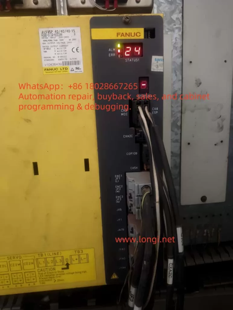
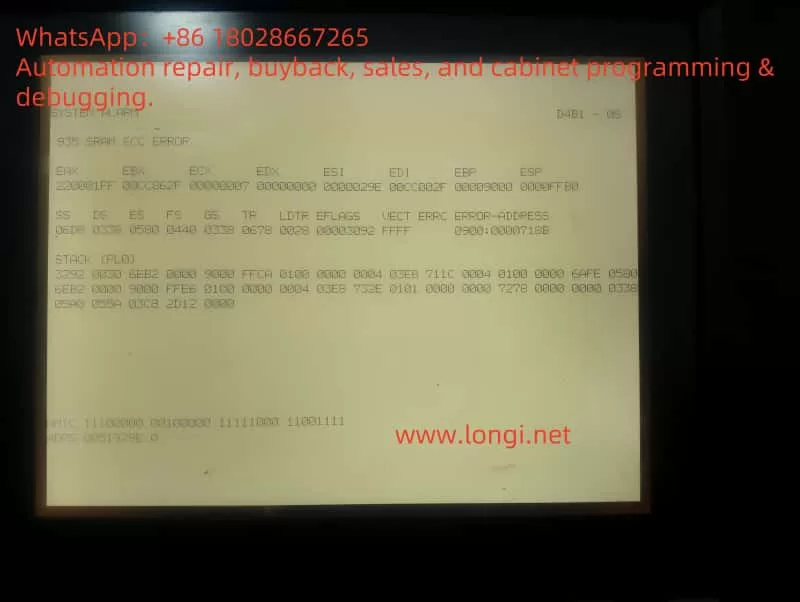
One of the most common alarms in the FANUC system is the 935 SRAM ECC error. This alarm indicates an error in the system’s SRAM module, typically caused by a faulty memory module or data corruption. Another common alarm is ALM 24, which usually signifies a serial communication failure between the main control system and the servo drive. This type of alarm may arise due to poor cable connections, a faulty servo drive communication port, or unstable power supply, among other reasons.
These alarm codes enable maintenance personnel to quickly identify the location and possible causes of the fault, allowing them to take appropriate maintenance measures. Below, we will explore in detail how to troubleshoot and resolve these common faults from the perspective of fault diagnosis and analysis, incorporating specific maintenance examples.
II. Fault Diagnosis and Maintenance for the 935 SRAM ECC Error
The 935 SRAM ECC error indicates a fault in the Static Random Access Memory (SRAM) module of the system. SRAM is a critical component for storing control programs, and its failure directly impacts system operation.
Fault Cause Analysis
- Insufficient Battery Voltage: The SRAM module in the FANUC system typically relies on battery power. If the battery voltage is insufficient, it may lead to data loss or corruption in the SRAM module.
- SRAM Module Failure: Over time, the SRAM module may fail due to physical damage or aging, resulting in an inability to read data correctly.
- Circuit Faults: Issues in the connecting circuit between the SRAM module and the motherboard may also cause data transmission errors, triggering the alarm.
Maintenance Steps
- Check Battery Voltage:
- First, check the battery voltage of the SRAM module. If the voltage is insufficient, replace the battery. After replacement, observe whether the alarm is resolved. If the battery voltage is normal but the alarm persists, further investigation is required.
- Initialize the SRAM Module:
- If the battery voltage is normal, attempt to initialize the SRAM. This can be done by pressing the device’s initialization button or performing a soft reset in the system to clear erroneous data from the memory. Subsequently, verify if the system can operate normally by restoring backup data.
- Replace the SRAM Module:
- If the above steps do not resolve the issue, the SRAM module itself may be faulty. In this case, replace the SRAM module. Ensure that the new module has the same specifications as the old one and perform necessary configurations.
Common Issues and Precautions
- When replacing the SRAM module, ensure that a backup of important control programs is made to prevent data loss.
- If the device does not respond during initialization, try forcing a restart.
III. Fault Diagnosis and Maintenance for the ALM 24 Alarm
The ALM 24 alarm indicates a serial communication failure between the main control system and the servo drive. This is manifested by the main control system’s inability to exchange data with the servo drive, resulting in the device’s inability to function properly.
Fault Cause Analysis
- Communication Cable Faults: The ALM 24 alarm is often caused by loose, poorly connected, or damaged communication cables between the controller and the drive. Any cable failure will interrupt data transmission, preventing the system from operating normally.
- Drive or Main Control System Communication Port Faults: If the communication ports of the servo drive or the main control system fail, it may also prevent the establishment of effective communication.
- Power Issues: Unstable or low voltage power supplies can also lead to communication errors. Ensuring that the device’s power voltage remains stable within the normal range is crucial.
Maintenance Steps
- Check Communication Cable Connections:
- First, inspect the communication cables between the main control system and the servo drive for looseness, damage, or poor contact. If any issues are found with the cables, replace or repair them promptly.
- Check Drive and Controller Communication Ports:
- If the cables are没有问题 (no issues), proceed to inspect the communication ports of the servo drive and the main control system. Determine if there are any port faults by replacing interface boards or checking the firmness of the interface connections.
- Check Power Supply Voltage:
- Ensure that the device’s power supply voltage is stable. If there are fluctuations or instability in the power supply, it may also cause communication faults. Check the power lines to ensure that the voltage is within the allowed range.
Common Issues and Precautions
- If the issue persists after replacing the cables and checking the ports, it is recommended to check the firmware versions of the drive and the main control system to ensure compatibility.
- When troubleshooting, do not overlook the device’s power issues, as unstable power may be the root cause of various faults.
IV. Summary
Fault diagnosis and maintenance of the FANUC system require a comprehensive understanding of the system’s structure and operating principles. When faced with the 935 SRAM ECC error and the ALM 24 alarm, it is essential to start by investigating common issues such as battery problems, communication line issues, and power problems, gradually identifying the source of the fault. Through systematic inspection and maintenance, the normal operation of the equipment can be effectively restored, ensuring the smooth progress of production.
Through this case analysis, it is evident that timely and accurate fault diagnosis and handling are key to resolving various alarms and faults in the FANUC system. Maintenance personnel should possess a solid technical foundation and flexibly utilize system analysis tools to find the best solutions when confronted with complex issues.