Introduction
Polarimetry is an important analytical technique widely applied in pharmaceuticals, food, chemistry, sugar production, and research laboratories. Substances that can rotate the plane of polarized light are called optically active. By measuring this rotation, information such as concentration, purity, or specific rotation of the sample can be obtained.
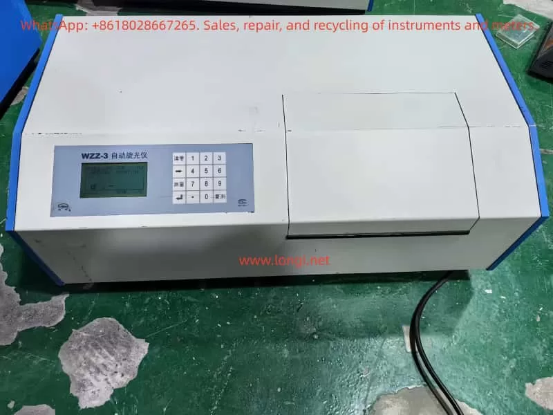
The WZZ-3 Automatic Polarimeter, manufactured by Shanghai Shenguang Instrument Co., Ltd., is a modern optical instrument that adopts the photoelectric automatic balance principle. Compared with manual polarimeters, it eliminates human reading errors, improves accuracy, and allows direct digital display of results. The instrument is equipped with multiple measurement modes, temperature control functions, and digital data interfaces, making it suitable for high-precision laboratory analysis.
This guide aims to provide a comprehensive reference for users by covering:
- Principle and features of the WZZ-3 polarimeter
- Temperature control methods
- Calibration and adjustment procedures
- Operation and routine maintenance
- Common faults and troubleshooting methods
I. Principle and Main Features
1.1 Working Principle
The WZZ-3 polarimeter works based on the photoelectric automatic balance method. The measurement process can be summarized in the following steps:
- Light Source
- The WZZ-3 typically uses a high-stability LED combined with an interference filter to provide a monochromatic beam close to the sodium D line (589.44 nm).
- Some older models use a sodium lamp.
- Polarization System
- The monochromatic light passes through a polarizer, producing linearly polarized light.
- When the polarized light passes through an optically active substance (such as sugar solution, amino acid, or pharmaceutical compound), its polarization plane is rotated by a certain angle.
- Analyzer and Detection
- At the analyzer end, a photoelectric detector receives the rotated polarized light.
- The change in light intensity is converted into an electrical signal.
- Automatic Balance
- The microprocessor adjusts the analyzer position automatically until light intensity reaches balance.
- The rotation angle is calculated and displayed digitally as optical rotation, specific rotation, concentration, or sugar content.
1.2 Main Features
- Multi-function Measurement: Supports direct measurement of optical rotation, specific rotation, concentration, and sugar content.
- High Precision: Resolution up to 0.001°; repeatability ≤ 0.002°.
- Automatic Operation: Automatically performs multiple measurements and calculates average values.
- Temperature Control: Built-in temperature control ensures stable measurement conditions.
- Digital Display and Output: Large LCD screen for real-time display; RS-232/USB interface for data transfer.
- User-friendly: Simplified operation, reduced manual intervention, and minimized reading errors.
II. Temperature Control System
Optical rotation is temperature-dependent. Even small temperature changes can lead to measurable variations. The WZZ-3 is equipped with temperature control functions to ensure reliable and repeatable measurements.
2.1 Temperature Control Components
- Sample Compartment with Jacket: Allows connection to a circulating water bath for precise control.
- Built-in Heating Unit: Some models include an electric heater and sensor for direct temperature regulation.
- Temperature Sensor: Monitors real-time sample temperature and provides feedback to the control system.
2.2 Control Range and Accuracy
- Control Range: 15 ℃ – 30 ℃
- Accuracy: ±0.5 ℃
2.3 Usage Notes
- Preheat the instrument until both the light source and the temperature control system stabilize.
- Ensure stable water circulation when using an external water bath.
- For high-precision tests, always use a thermostatic water bath together with temperature-controlled sample tubes.
- After use, drain water lines promptly to prevent scale buildup.
III. Calibration and Adjustment
3.1 Zero Adjustment
- Turn on the instrument and allow 15–20 minutes for preheating.
- Insert an empty sample tube (or keep the cell empty).
- Select the Optical Rotation Mode and press the zero key to set the reading to 0.000°.
3.2 Calibration with Standard Sample
- Use the supplied quartz calibration plate or standard solution.
- Place it in the sample compartment and measure.
- Compare measured value with certified standard value:
- If deviation ≤ ±0.01°, calibration is valid.
- If deviation exceeds the tolerance, enter the calibration interface, input the standard value, and let the system adjust automatically.
3.3 Instrument Adjustment
- Verify that the light source is stable and sufficient in intensity.
- Ensure optical alignment so that the beam passes centrally.
- Re-measure the standard sample repeatedly to confirm consistency.
IV. Operation and Routine Maintenance
4.1 Operating Steps
- Sample Preparation
- Ensure the solution is homogeneous, transparent, and free of air bubbles or suspended particles.
- Power On and Preheating
- Start the instrument and allow adequate preheating time for light and temperature stabilization.
- Mode Selection
- Choose among optical rotation, specific rotation, concentration, or sugar content according to experimental requirements.
- Loading the Sample Tube
- Fill the tube without air bubbles; seal the ends properly.
- Measurement
- Press the measurement key; the instrument automatically performs multiple readings and calculates the average.
- Reading and Output
- View results on the LCD; if necessary, export data through the interface to a computer or printer.
4.2 Routine Maintenance
- Sample Compartment Cleaning: Clean regularly to prevent contamination.
- Optical Components: Do not touch with bare hands; clean with ethanol and lint-free cloth if necessary.
- Light Source: Inspect periodically; replace if intensity decreases significantly.
- Environmental Requirements: Keep away from direct sunlight, vibration, and high humidity.
- Long-term Storage: Switch off power, disconnect cables, and cover with a dust-proof cover.
V. Common Faults and Troubleshooting
5.1 Light Source Not Working
- Possible Causes: Lamp/LED damaged, power supply fault, or loose connection.
- Solution: Check power → inspect lamp → replace light source module.
5.2 Unstable Reading
- Possible Causes: Sample turbidity, temperature fluctuation, insufficient preheating.
- Solution: Use a filtered and homogeneous sample; extend preheating; apply thermostatic bath.
5.3 Large Measurement Deviation
- Possible Causes: Not calibrated, expired standard sample, or improper zero adjustment.
- Solution: Re-zero the instrument; calibrate with quartz plate; replace standards.
5.4 Communication Failure
- Possible Causes: Interface damage, incorrect baud rate, faulty cable.
- Solution: Verify port configuration; replace cable; check PC interface.
5.5 Temperature Control Failure
- Possible Causes: Faulty temperature sensor, unstable water circulation.
- Solution: Inspect circulation system; check sensor connection; replace if necessary.
VI. Conclusion
The WZZ-3 Automatic Polarimeter is a high-precision, multi-functional instrument widely used for analyzing optically active substances. Its strengths lie in:
- Photoelectric automatic balance technology
- Accurate temperature control
- Multi-mode measurement capability
- Digital display and data communication
To ensure reliable results, users should pay special attention to:
- Calibration procedures (zero adjustment and standard sample calibration)
- Temperature stability (always use thermostatic control for critical experiments)
- Sample preparation (avoid bubbles and impurities)
- Routine maintenance (cleaning, light source inspection, and storage conditions)
By following the outlined procedures and troubleshooting methods, users can maintain the instrument’s accuracy, extend its lifespan, and ensure consistent performance in laboratory applications.