
Operation Panel Function Introduction
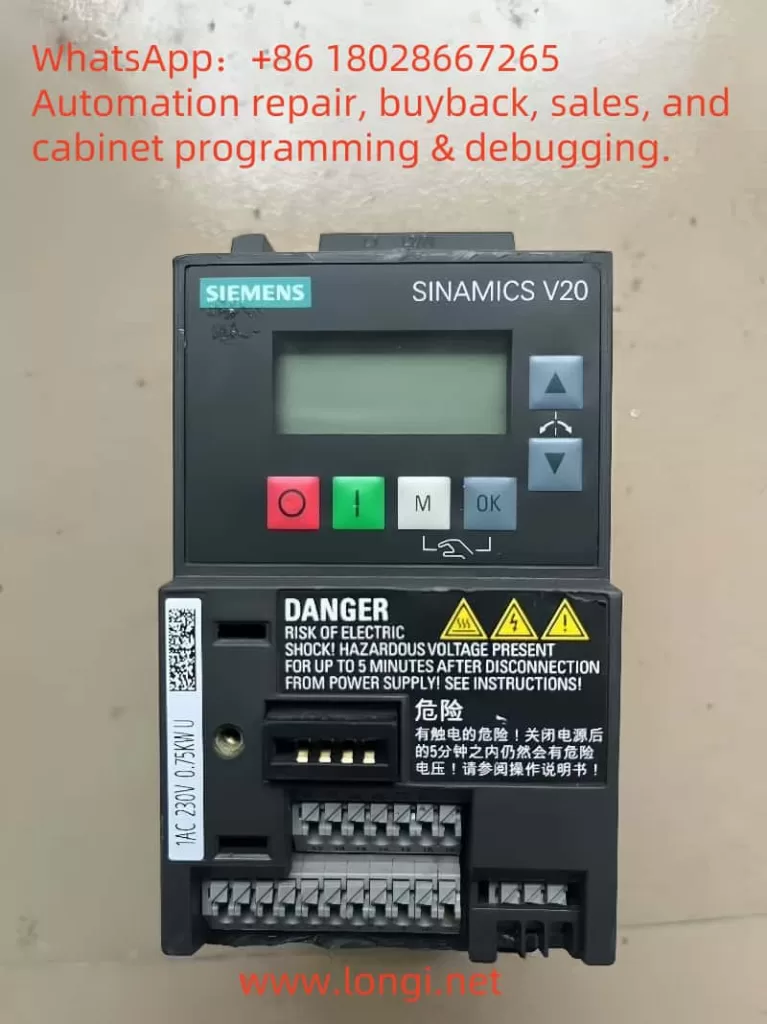
The Basic Operation Panel (BOP) of the Siemens V20 frequency converter serves as the primary interface for user interaction, integrating multiple critical functions. It provides real-time monitoring of key parameters including operating frequency, output current, and DC bus voltage, displayed on a high-brightness LED screen with two-line readability up to 1.5 meters. The membrane keypad design includes six functional keys:
- OFF1 Stop Key: Initiates ramp stop by single press, decelerating the motor to stop according to preset deceleration time (P1121).
- Start/Reverse Key: Controls motor start/stop in manual mode, with long-press (2 seconds) for direction reversal.
- Multi-Function Key (M): Navigates menus, confirms parameter edits, switches display screens, and initiates bit editing when combined with OK key.
- OK Key: Enables mode switching, rapid parameter confirmation, and password entry (long-press for 3 seconds).
- Direction Keys: Traverses menu hierarchy, adjusts parameter values, and fine-tunes frequency settings; scrolls fault history in alarm state.
- Fault Reset Key: Integrated with OK key functions through combination operations.
The panel adopts a three-level menu structure with four main modules: Operation Status, Parameter List, Fault Records, and System Settings. In parameter editing mode, bit-by-bit modification is supported with rapid saving via OK key. Notably, the BOP supports offline parameter backup through dedicated interfaces.
Parameter Initialization and Security Settings
Parameter Initialization Procedure
The Quick Commissioning function enables parameter reset and basic configuration:
- Enter P0010=1 commissioning mode
- Configure motor parameters (P0304-P0311)
- Select connection macro (Cn001 for terminal control or Cn002 for communication control)
- Set application macro (e.g., P1300=20 for fan/pump loads)
- Execute P3900=1 to complete calculations
This process automatically configures over 20 core parameters including ramp functions and overload protection, reducing commissioning time by 60% compared to traditional methods.
Access Control Mechanism
The V20 converter employs a hierarchical access management system:
- Access Level (P0003): Five levels from 0 (user-defined) to 4 (service)
- Parameter Group Locking: Restricts accessible parameter groups via P0004
- Password Protection: 4-digit password required for critical parameter modifications at expert level (3)
To remove password protection, downgrade P0003 to level 2 or below, or reset via service interface using specialized tools. Access restrictions can be applied to individual parameters, such as allowing P1080 (minimum frequency) adjustments while blocking P1120 (acceleration time) modifications.
External Control Implementation
Forward/Reverse Terminal Control
Utilizing digital input terminals (DI1-DI4) for direction control:
- Wiring Configuration: Connect DI1 for forward command (24VDC) and DI2 for reverse command
- Parameter Settings:
- P0701=1 (DI1 as ON/OFF1 command)
- P0702=2 (DI2 as reverse command)
- P0700=2 (command source set to terminal control)
- P1000=3 (frequency source set to analog input)
This configuration supports pulse commands for forward/reverse operations, automatically executing deceleration-stop-reverse acceleration sequence to prevent mechanical shocks.
Potentiometer Speed Control
Implementing analog input terminal (AI1) for stepless speed regulation:
- Wiring Requirements: Connect 10kΩ linear potentiometer with mid-tap to AI1 (10V power supplied by converter)
- Parameter Configuration:
- P0756=2 (AI1 set to 0-10V voltage input)
- P1000=2 (frequency source set to analog input)
- P1080=5Hz (minimum frequency)
- P1082=50Hz (maximum frequency)
- P0759=0 (zero calibration)
- P0760=100% (full-scale calibration)
Input filtering time (P0771) is recommended at 50ms to suppress interference pulses from contactor operations.
Fault Diagnosis and Resolution
Typical Fault Code Reference
| Fault Code | Description | Possible Causes | Solutions |
|---|---|---|---|
| F1 | Overcurrent | Motor cable short, short acceleration time | Check insulation, extend P1120 |
| F3 | Undervoltage | Power supply fluctuation, braking resistor short | Verify power quality, check R0001 resistor |
| F4 | Converter Overheat | Poor ventilation, high pulse frequency | Clean air ducts, reduce P1800 carrier frequency |
| F12 | Temp Sensor Fault | Temperature detection circuit open | Check T1/T2 terminal connections |
| F54 | Motor I²t Overload | Prolonged overload operation | Reduce load, adjust P610 thermal time constant |
| F79 | Motor Stall | Mechanical jamming, sudden load change | Check transmission, optimize P1237 stall detection time |
Systematic Fault Handling
- Fault Verification: Check current fault code and timestamp via BOP
- Parameter Backup: Execute P0971=1 to prevent data loss during troubleshooting
- Root Cause Analysis:
- Electrical Issues: Measure terminal resistance (phase-to-phase insulation >1MΩ)
- Mechanical Issues: Verify coupling alignment (allowable deviation <0.05mm)
- Parameter Anomalies: Compare with P0005 parameter change history
- Recovery Procedure:
- Temporary Fix: Restore factory settings via P0970=1 (after backup)
- Permanent Repair: Replace components or optimize control logic per fault code guidance
Maintenance and Optimization Recommendations
- Preventive Maintenance:
- Clean cooling fans every 2000 operating hours
- Calibrate potentiometer linearity quarterly (error <2%)
- Perform insulation resistance test annually (≥1MΩ@500VDC)
- Energy Efficiency:
- Enable P1300=20 fan/pump macro for automatic V/f² characteristic
- Match P1120/P1121 ramp times with load inertia
- Activate P3300=1 energy-saving mode for automatic frequency reduction at no-load
- Communication Expansion:
- Enable USS protocol via P2010[0]=1
- Configure P2011=9.6kbps baud rate
- Set Modbus address mapping using P2021-P2024
This guide is based on V20 firmware version V4.7.16. Always refer to the manual corresponding to your device’s firmware version. Execute parameter backup via P0971=1 before critical modifications and manage versions with P0970=2. For complex applications, use STARTER tool for offline programming and online monitoring.