
Introduction
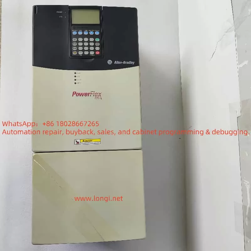
Rockwell Automation, a global leader in industrial automation solutions, is well-regarded for its high-performance and reliable PowerFlex series inverters. The PowerFlex 700 series, suitable for various applications such as machine tools, conveyor systems, fans, and pumps, is widely used in industrial settings. However, in complex industrial environments, inverters may encounter faults due to various reasons, with the F085 fault code being a common issue faced by users. This article provides a detailed analysis of the meaning, causes, and solutions for the F085 fault based on the PowerFlex 700 series inverter user manual (Chinese version) and relevant technical resources, offering practical guidance to users.
Meaning of the F085 Fault Code
According to the PowerFlex 700 series inverter user manual (Chinese version), the F085 fault code indicates an “External Fault.” This fault is triggered by an abnormal signal sent to the inverter via a digital input (DI) from an external device. When the inverter detects an abnormal signal from an external device (such as a PLC, sensor, or other control device) through its digital input terminals, it triggers the F085 fault, leading to inverter shutdown or an alarm.
It is important to note that some English versions of the manual may describe F085 as “DPI Port 1-5 Loss,” indicating potential variations in fault code descriptions across different versions or languages. This article adheres to the Chinese manual provided by the user, defining F085 as an “External Fault.” Users should confirm the manual version in actual operations to ensure accuracy in fault code interpretation.
Causes of the F085 Fault
The triggering of the F085 fault is typically related to external devices, wiring, or inverter configuration. The following are possible causes:
External Device Failure
- External devices connected to the inverter’s digital inputs, such as PLCs or sensors, may send erroneous signals due to hardware failures or misoperations. For example, sensors may output abnormal signals due to environmental interference or damage.
- Incorrect configuration of external devices (e.g., PLC program logic errors) may also lead to the inverter misinterpreting signals as external faults.
Wiring Issues
- Wiring between external devices and the inverter’s digital input terminals may be loose, short-circuited, or open-circuited, resulting in abnormal signal transmission.
- Dust, corrosion, or mechanical vibration affecting the wiring terminals may cause poor contact.
Parameter Configuration Errors
- The inverter’s digital input parameters (e.g., parameters 361-366 for “Digital Input 1-6 Selection”) may not be correctly configured, leading to the inverter misinterpreting external signals.
- If digital inputs are set to detect external faults but the external devices do not correctly match the signal logic, the F085 fault may be triggered.
HIM (Human-Machine Interface) Connection Problems
- If an HIM is used for control, unstable connections between the HIM and the inverter may result in signal transmission interruptions or false fault triggers.
- Damage to the HIM device itself may also indirectly affect fault detection.
External Signal Logic Issues
- The signal logic (e.g., high or low level) sent by external devices may not match the inverter’s expectations, leading to false triggers of the F085 fault.
Solutions for the F085 Fault
To effectively resolve the F085 fault, users can follow these steps for troubleshooting and handling:
1. Check External Devices
Steps: Inspect external devices connected to the inverter’s digital inputs (e.g., PLCs, sensors) for normal operation.
Operations:
- Confirm whether the devices are sending fault signals and check their status for normal operation.
- If a device outputs a fault signal, verify whether it is a genuine fault or a false alarm.
- Replace or repair external devices as necessary.
Note: Ensure that the operating environment of the devices (e.g., temperature, humidity) meets requirements to avoid interference.
2. Check Wiring
Steps: Verify that the wiring between external devices and the inverter’s digital input terminals is secure.
Operations:
- Check for loose, short-circuited, or open-circuited wiring terminals.
- Use a multimeter to test wiring continuity and ensure no poor contact exists.
- Refer to the user manual’s wiring diagrams to ensure compliance with specifications.
Note: Disconnect the power supply before operations to ensure safety.
3. Verify HIM Connection
Steps: If an HIM is used for control, check the connection between the HIM and the inverter.
Operations:
- Ensure that the HIM connection cables are secure and that the connection ports are clean.
- Try reinserting the HIM or replacing the HIM device.
Note: HIM connection issues may indirectly affect fault triggers and require careful troubleshooting.
4. Check and Adjust Parameter Settings
Steps: Access the inverter’s parameter setup menu and check digital input-related parameters.
Operations:
- Check parameters 361-366 (Digital Input 1-6 Selection) to confirm which input triggered the F085 fault.
- If external fault detection is not required, set the relevant parameters to “Disabled” or “No Function” (e.g., set to 0).
- Check parameters 17 (Digital Input Configuration) and 18 (Digital Input Logic) to ensure signal logic matches.
Example Parameter Table:
| Parameter Number | Description | Possible Settings |
|---|---|---|
| 361-366 | Digital Input 1-6 Selection | Set to 0 (No Function) to disable external fault |
| 17 | Digital Input Configuration | Ensure matching with external device signals |
| 18 | Digital Input Logic | Adjust logic (e.g., high/low level) |
5. Adjust Fault Mask Parameters
Steps: Check fault mask parameters to屏蔽 (mask) the F085 fault.
Operations:
- Locate parameter 4 (External Fault) or relevant fault mask parameters.
- Set it to “Disabled” (e.g., 0) to prevent the F085 fault from triggering shutdown or an alarm.
- Save parameter settings (usually through parameter 30 “Parameter Save”).
Note: Specific parameter values should be referenced from the user manual.
6. Reset the Fault
Steps: After resolving the issue, clear the fault.
Operations:
- Select the “Fault Clear” option through the HIM or control panel.
- Alternatively, power off and restart the inverter (ensure safe operation).
Note: Ensure that the root cause has been resolved before resetting.
7. Further Diagnosis
Steps: If the issue remains unresolved, use diagnostic tools or contact technical support.
Operations:
- Use a SCANport device to check the communication status between the inverter and external devices.
- Contact us for professional assistance.
Preventive Measures
To prevent the recurrence of the F085 fault, the following measures can be taken:
Regular Maintenance
- Regularly inspect external devices and wiring status to ensure reliable connections.
- Clean wiring terminals to prevent dust or corrosion from affecting signal transmission.
Correct Parameter Configuration
- During initial setup, ensure that digital input parameters match external devices.
- If external fault detection is not used, disable relevant functions in advance.
Monitor System Status
- Regularly check the inverter’s operating status using an HIM or other tools and record abnormal logs.
- Establish a fault warning mechanism to detect potential issues promptly.
Train Operators
- Provide training to ensure that operators are familiar with inverter operation and fault handling.
- Update knowledge of new manual versions and parameter settings.
Backup System Configuration
- Regularly back up inverter parameters for quick recovery after faults.
Conclusion
The F085 fault in the PowerFlex 700 series inverter typically indicates an “External Fault” triggered by an external device via a digital input. By checking external devices, wiring, parameter settings, and making necessary adjustments, the fault can be effectively resolved. Regular maintenance and correct configuration are key to preventing faults. Users should refer to specific chapters in the PowerFlex 700 user manual (Chinese version) and conduct troubleshooting based on actual application scenarios. If the issue is complex, it is recommended to contact us for further guidance.