
I. Panel Function Introduction and Parameter Management Operations
1. Panel Function Introduction
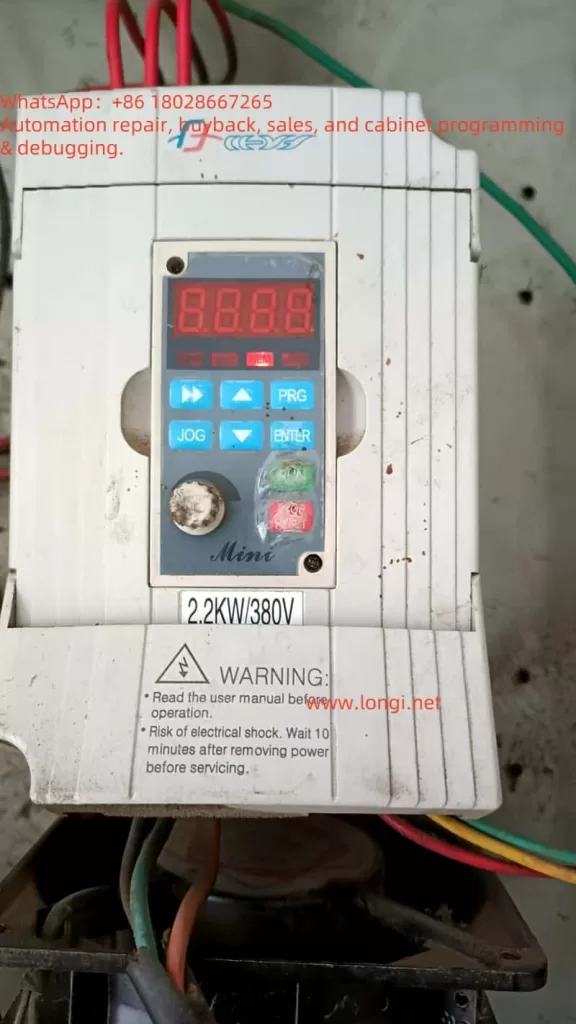
The operation panel of the RiHong CHRH-G series inverter includes the following core buttons and indicators:
- RUN Key: Starts the inverter operation, defaulting to forward rotation.
- STOP/RESET Key: Stops the machine or resets faults.
- PRG Key: Enters parameter setting mode.
- ENTER Key: Saves parameter modifications.
- ▲/▼ Keys: Adjusts parameter values or switches monitoring items.
- ◄/► Keys: Modifies parameter digits or switches function groups.
- Analog Potentiometer: Manually adjusts frequency (requires setting the frequency reference channel to potentiometer mode).
LED Indicator Descriptions:
- Hz: Displays frequency unit.
- A/V: Displays current or voltage unit (green for current, red for voltage).
- ALM: Fault alarm indicator (red constantly lit or flashing).
- F/R: Rotation direction indicator (red for forward, green for reverse).
2. Parameter Factory Default Settings
Steps:
- Enter function code F0.13 (Parameter Initialization).
- Set to 1 (Restore factory settings, retaining motor parameters) or 2 (Restore all parameters).
- Press the ENTER key to confirm; the system will automatically exit after completion.
3. Parameter Encryption and Decryption
Encryption Setup:
- Enter function code FC.05 (User Password) and set a password (range: 10~65535).
- Set function code F0.14 (Parameter Write Protection) to 2 (Prohibit modification of all parameters).
Decryption Operation:
- After entering the correct password, set F0.14 to 0 or 1 to lift the protection.
4. Parameter Access Restrictions
Set access permissions via F0.14:
- 0: Allows modification of all parameters (in stop state).
- 1: Only allows modification of frequency-related parameters (F0.02~F0.08).
- 2: Completely prohibits modification of parameters.
II. External Terminal Forward/Reverse Control and Potentiometer Speed Regulation
1. External Terminal Forward/Reverse Control
Wiring Terminals:
- X1/X2/X3: Multi-function input terminals (default functions need redefinition).
- COM: Common terminal.
Parameter Settings:
- Set F0.01 (Operation Command Channel) to 1 (Terminal Control).
- Set F5.00 (X1 Function) to 12 (Forward Control) and F5.01 (X2 Function) to 13 (Reverse Control).
- The corresponding direction starts when the terminal is closed and stops when disconnected.
2. External Potentiometer Speed Regulation
Wiring Terminals:
- AI1: Analog Input 1 (0~10V/0~20mA).
- GND: Signal ground.
Parameter Settings:
- Set F0.02 (Frequency Reference Channel) to 4 (AI1 Analog Reference).
- Calibrate the AI1 input range via F6.00~F6.03 (default: 0~10V corresponds to 0~maximum frequency).
- Adjust the potentiometer to regulate the output frequency in real-time.
III. Fault Code Analysis and Solutions
| Fault Code | Meaning | Possible Causes | Solutions |
|---|---|---|---|
| E001 | Acceleration Overcurrent | Acceleration time too short, sudden load change | Extend acceleration time, check load |
| E005 | Deceleration Overvoltage | Deceleration time too short, inertial load | Extend deceleration time, install braking resistor |
| E009 | Power Module Fault | Output short circuit, poor heat dissipation | Check motor wiring, clean air ducts |
| E010 | Heatsink Overheating | High ambient temperature, fan failure | Improve ventilation, replace fan |
| E013 | External Device Fault | External fault signal input | Check external device wiring |
| E021 | Operation Time Limit Reached | Cumulative operation timeout | Contact dealer to lift restriction |
| E022 | Output Phase Loss | Loose or broken motor wiring | Check U/V/W terminal connections |
General Fault Handling Steps:
- Press the STOP/RESET key to reset.
- Check monitoring parameters (d-21~d-28) to record the operating state during the fault.
- Adjust relevant parameters or check hardware connections according to the manual.
IV. Maintenance and Precautions
Daily Maintenance:
- Regularly clean the heat dissipation air ducts to ensure proper fan operation.
- Check terminal screws for looseness to avoid poor contact.
Insulation Testing:
- Disconnect all wiring, short-circuit the main circuit terminals, and test with a 500V megohmmeter.
- Do not perform insulation tests on control terminals.
Long-Term Storage:
- Store in a dry environment and power on every six months to activate electrolytic capacitors.
Conclusion
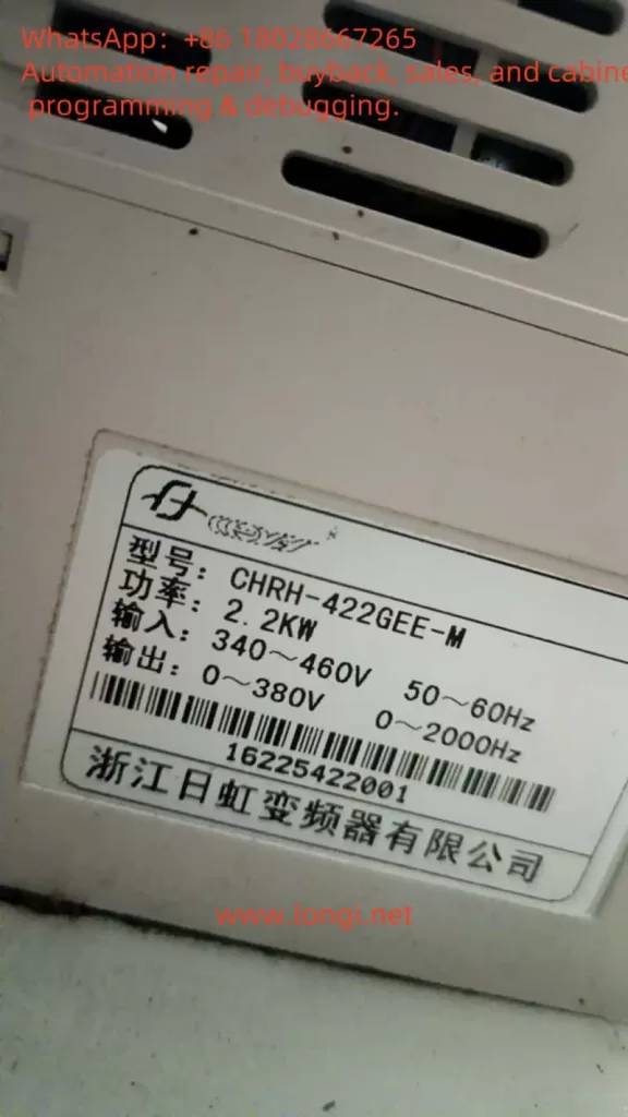
The RiHong CHRH-G series inverter meets diverse industrial scenario demands through flexible terminal control, parameterized configuration, and multiple protection functions. Users must master panel operations, parameter logic, and fault troubleshooting methods to ensure efficient and stable operation of the equipment. For complex issues, it is recommended to contact the manufacturer’s technical support for professional guidance.