

Description
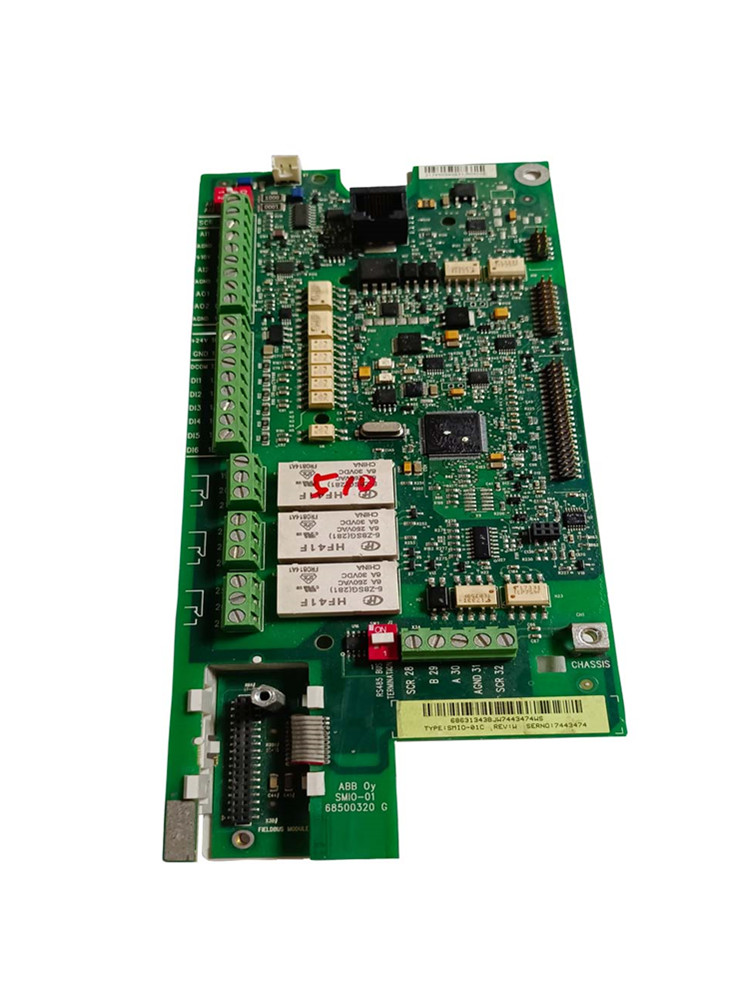
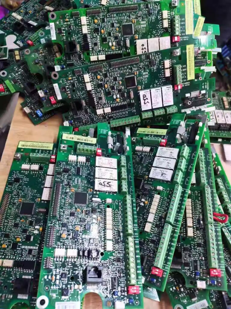
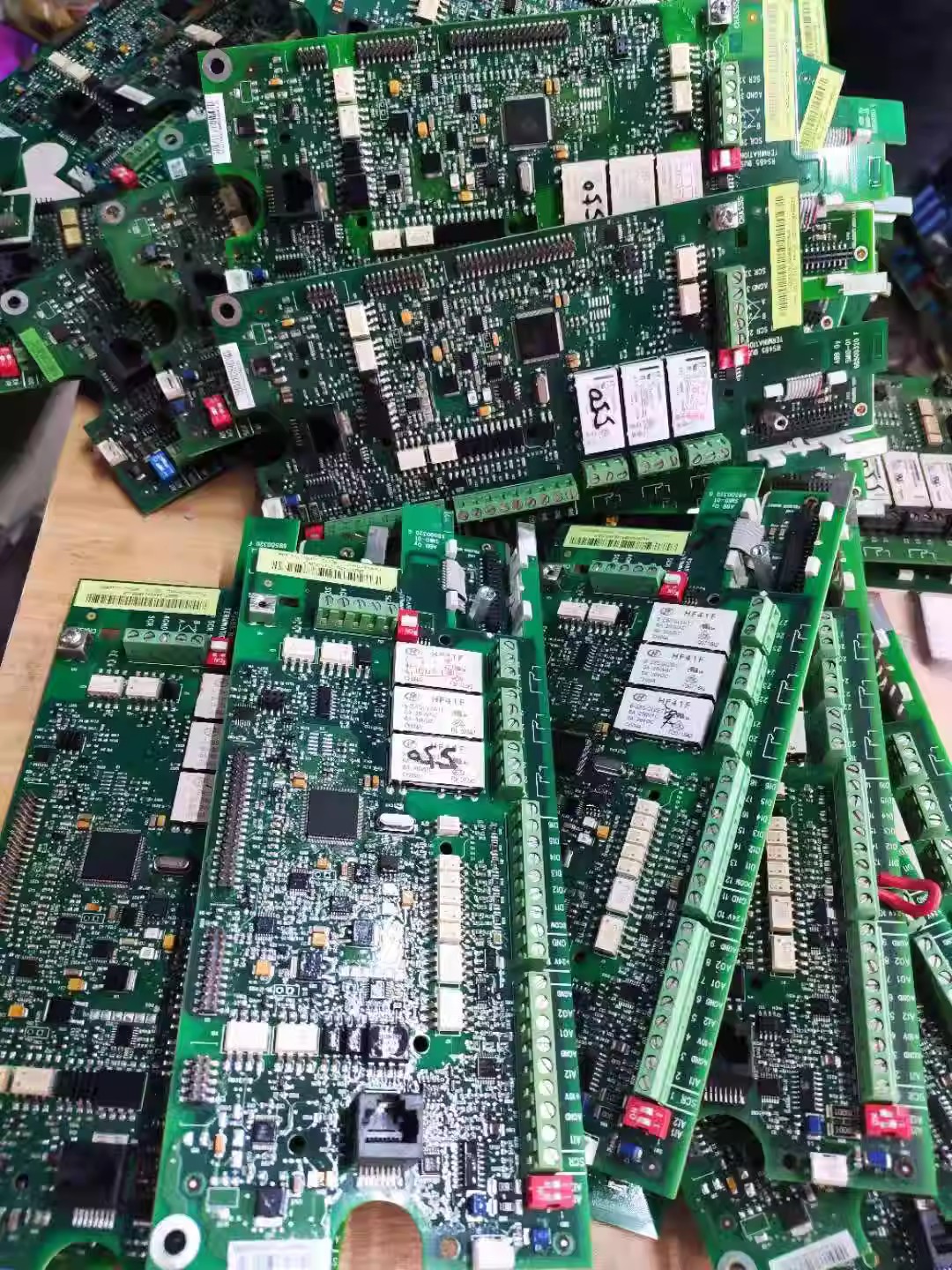
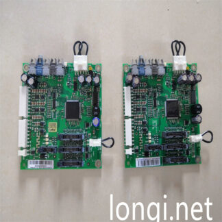
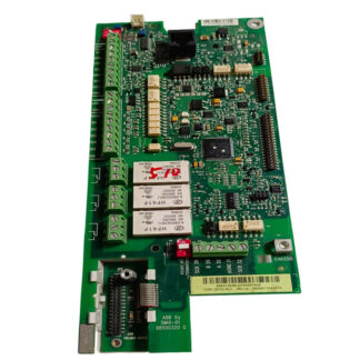
Used ACS510/ACS550/ACH550 Inverter motherboard IO board CPU board SMIO-01C/OMIO-01C, functioning normally,Good quality and stable quality,Suitable for ABB’s AC VFD drive ACS510/ACS550/ACH550 with any power,You can adjust the power of this board yourself.
Due to the different power of the frequency converter every Model, this CPU board needs to be changed after purchase. If you do not understand how to change the power, please leave a message about the power size of the VFD driver, such as ACS510-01-025A-4 (11KW), We can help you adjust the power before shipping.
Common ABB DRIVE ACS510/ACS550/ACH550 VSD/VFD fault codes list,If you need further solutions or a detailed PDF manual, you can contact us directly,We will provide you with free online solutions to ABB driver faults.
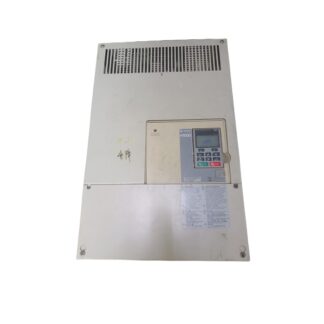
The common ABB driver ACS510/ACS550/ACH550 failure is caused by the driver board, but due to the design of this driver, problems with the driver board often lead to motherboard failures. While repairing the driver board, it is necessary to directly replace the motherboard to cooperate.
When ABB drive ACS510/ACS550/ACH550 malfunctions, it is necessary to search for the code meaning of the fault according to the fault list below, and prescribe the right medicine to solve the problem. Common faults include unresponsive transmission, overcurrent, overheating, no display, undervoltage, etc., which need to be handled in conjunction with the on-site situation.
F001 OVERCURRENT
The output current is too high. Inspection and troubleshooting:
Motor overload.
The acceleration time is too short (parameters 2202 ACCESSER TIME 1 and 2205)
Accelerator Time 2.
Motor failure, motor cable failure or wiring error.
F002 DC OVERVOLT
The DC voltage of the intermediate circuit is too high. Inspection and troubleshooting:
The power supply on the input side experiences static or transient overvoltage.
The deceleration time is too short (parameters 2203 DECELER TIME 1 and 2206 DECELER
TIME 2 (deceleration time 2).
The selection of brake chopper is too small (if any).
Confirm that the overvoltage controller is in normal working condition (using parameter 2005).
F003 DEV OVERTEMP
Radiator overheating. The temperature reaches or exceeds the limit value.
R1~R4:115 ° C
R5/R6: 125 ° C
Inspection and troubleshooting:
Fan failure.
Air circulation is obstructed.
Dust accumulation in the radiator.
The ambient temperature is too high.
The motor load is too large.
F004 SHORT CIRC
Short circuit fault. Inspection and troubleshooting:
Motor cable or motor short circuit.
Power supply disturbance.
F005 RESERVE
Unused.
F006 DC UNDERVOLT
Insufficient DC voltage in the intermediate circuit. Inspection and troubleshooting:
The power supply is out of phase.
The fuse is blown.
The main power supply is under voltage.
F007 AI1 LOSS
Analog input 1 is missing. The analog input value is less than parameter 3021 AI1FLT Limit
Value. Inspection and troubleshooting:
Analog input signal source and its wiring.
Set parameter 3021 AI1FLT Limit and check
3001 AI<MIN ACTION (AI Fault Function).
F008 AI2 LOSS
Analog input 2 is missing. The analog input value is less than the parameter 3022 AI2 FLT Limit
Value. Inspection and troubleshooting:
Analog input signal source and its wiring.
Set parameter 3022 AI2 FLT Limit and check
3001 AI<MIN ACTION (AI Fault Function).
F009 MOT TEMP
Motor overheating, based on transmission estimation or temperature feedback signal.
Check if the motor is overloaded.
Adjust the parameters used for estimation (3005-3009).
Check the temperature sensor and parameter settings in parameter group 35.
F0010 PANEL LOSS
Control panel communication lost, and:
The transmission is under local control (the control panel displays LOC, local), or
The transmission is in remote control mode (REM, remote), and the start/stop/direction/given value signal comes from the control
Disc making.
Inspection:
• Communication links and wiring.
Parameter 3002 PANEL COMM ERROR.
Parameters of parameter array 10: control command input and given selection in parameter group 11 (transmission unit running on
REM (remote) mode.
F0011 RESERVE
Unused.
F0012 MOTOR STALL
Motor or process stall. The motor operates in a locked rotor area. Check the following:
Overload.
The motor power is insufficient.
Parameters 3010 to 3012.
F0013 RESERVE
Unused.
F0014 EXTERNAL FLT 1
The digital input corresponding to the first external fault alarm is activated. Refer to parameter 3003 Extended Fault 1
(External fault 1).
F0015 EXTERNAL FLT 2
The digital input corresponding to the second external fault alarm is activated. Refer to parameter 3004 Extended Fault 2
(External Fault 2).
F0016 EARTH FAULT
Possible ground faults detected at the motor or motor cable. Monitor when the transmission is running or stopped
Ground fault. The sensitivity of ground fault detection is higher when the transmission stops, and it can report the occurrence of faults
Location of.
Corrective measures:
Check/troubleshoot incoming grounding faults.
Ensure that the length of the motor cable does not exceed the maximum allowed length.
If the input power supply is connected in a triangle and the capacitance of the input power cable is large, it may cause
Ground fault false alarm in case of transmission stop. If you want to disable fault detection when the transmission stops
Function, using parameter 3023 WIRING Fault. All grounding should be prohibited
For obstacle detection function, please use parameter 3017.
F0017 RESERVE
Unused.
F0018 THERM FAIL
Internal fault. Monitor the internal temperature thermistor of the transmission for disconnection or short circuit.
F0019 OPEX LINK
Internal fault. A communication issue has been detected between the OMIO and OITFA boards.
F0020 OPEX PWR
Internal fault, under voltage detected on OITF board.
F0021 CURR MEAS
Internal fault, current measurement out of range.
F0022 SUPPLY PHASE
The ripple voltage of the DC circuit is too high, check the following two items:
The main power supply is out of phase.
The fuse is blown.
F0023 Attachment Issues
If this error code appears, search for the relevant attachment manual.
F0024 Reserve
Unused
F0025 Reserve
Unused
F0026 DRIVE ID Transmission identification number
Internal fault. The frequency converter ID configuration is invalid.
F0027 CONFIG FILE
Internal configuration file error.
F0028 SERIAL 1 ERR
Fieldbus communication timeout. Check the following:
• Fault settings (3018 COMM Fault FUNC and 3019 COMM Fault
TIME (communication failure time).
Communication settings (whether the settings for group 51 or 53 are appropriate).
The communication link connection is poor or there is interference.
F0029 EFB CONFIG FILE
An error occurred while reading the configuration file on the embedded fieldbus.
F0030 FORCE TRIP
Forced fault shutdown by fieldbus. Refer to the fieldbus user manual.
F0031 EFB 1
Fault codes reserved for embedded fieldbus (EFB) protocol applications. Different protocols are used,
The meaning of fault codes is also different.
F0032 EFB 1
Fault codes reserved for embedded fieldbus (EFB) protocol applications. Different protocols are used,
The meaning of fault codes is also different.
F0033 EFB 1
Fault codes reserved for embedded fieldbus (EFB) protocol applications. Different protocols are used,
The meaning of fault codes is also different.
F0034 MOTOR PHASE
The motor circuit is faulty. The motor is out of phase. Check the following:
Motor failure.
Motor cable fault.
Thermal relay malfunction (if used).
Internal faults
F0035 OUTPUT WIRING
Power wiring error. When the transmission stops, this fault code monitors the input power cable and output of the transmission
Correct connection of power cables. Check the following two items:
The input cable is connected correctly – the power supply voltage is not connected to the transmission output.
If the input power cable is connected in a triangular shape and the capacitance of the input power cable is relatively large, then
There may be false alarms of ground faults. Using parameter 3023 WIRING Fault
The fault detection function can be disabled.
F0036 INCOMP SWTYPE
The software version is not compatible, and the transmission cannot use the software.
Internal fault.
The installed software is not compatible with the transmission.
F0037 CB OVERTEMP
The temperature of the control board exceeds 88 degrees Celsius. Inspection and correction methods:
The ambient temperature is too high
Fan failure
• Poor air circulation
The OMIO board does not support this feature.
F0038 USER LOAD CURVE
User defined load curve failure. Refer to parameter group 37 settings.
F0101…109 SYSTEM ERROR
Internal transmission failure. Please contact us and provide the fault code.
F0201…209 SYSTEM ERROR
Internal transmission failure. Please contact us and provide the fault code.
*The following are the fault codes related to parameter setting conflicts:
F1000 PAR HZRPM
The parameter settings are inconsistent. Check the following:
2007 MINIMUM FREQ>2008 MAXIMUM FREQ.
2007 MINIMUM FREQ divided by 9907 MOTOR NOM FREQ
Fixed frequency) out of range (>50).
2008 MAXIMUM FREQ divided by 9907 MOTOR NOM FREQ
Fixed frequency) out of range (>50).
F1001 PAR PFC REFNEG
The parameter values are inconsistent. Inspection:
When 8123 PFC ENABLE is activated, the 2007 MINIMUM FREQ (minimum
The frequency is negative.
F1003 PAR AI SCALE
The parameter values are inconsistent. Check the following two items:
1301 AI 1 MIN (AI 1 lower limit)>1302 AI 1 MAX (AI 1 upper limit).
1304 AI 2 MIN (AI 2 lower limit)>1305 AI 2 MAX (AI 2 upper limit).
F1004 PAR AO SCALE
The parameter values are inconsistent. Check the following two items:
1504 AO 1 MIN (AO1 lower limit)>1505 AO 1 MAX (AO 1 upper limit).
1510 AO 2 MIN (AO 2 lower limit)>1511 AO 2 MAX (AO 2 upper limit).
F1005 PAR PCU 2
The parameter values used for power control are inconsistent: the rated capacity and motor rated power are incorrect. Check the following
Two items:
1.1<(9906 MOTOR NOM CURR * 9905 MOTOR NOM VOLT
(Rated voltage of motor) * 1.73/PN)<3.0
Here: PN=1000 * 9909 MOTOR NOM POWER (in kW). Or PN=746
*9909 MOTOR NOM POWER (in HP)
F1006 PAR EXT RO
The parameter values are inconsistent. Check the following two items:
The expansion relay module is not connected, and
1410-1412 Relay Outputs 4-6 have non-zero values.
F1007 PAR FIELDBUS MISSING
The parameter values are inconsistent. Check this item:
There is a parameter set to fieldbus control (such as 1001 EXT1 COMMANDS (external 1 command
Command=10 (communication), but 9802 COMM PROT SEL (communication protocol selection)=0.
F1008 Reserved
F1009 PAR PCU1
The parameter values used for power control are inconsistent, and the rated frequency or speed are incorrect. Check the following two items:
1<(60 * 9907 MOTOR NOM FREQ motor rated frequency/9908 MOTOR NOM SPEED
Motor rated speed<16
0.8<9908 MOTOR NOM SPEED motor rated speed/
(120 * 9907 MOTOR NOM FREQ motor rated frequency/Motor Poles motor pole number)<
zero point nine nine two
F1011 PAR OVERRIDE
Parameter group 17 is set incorrectly.
F1012 PAR PFC IO 1
Incomplete IO configuration – insufficient number of relays assigned as PFC. Or in parameter group 14
Parameter 8817 NR OF AUX MOT and Parameter 8118 AUTOCHNG INTERV
There is a conflict between (automatic switching interval)
F1013 PAR PFC IO 2
Incomplete IO configuration – actual number of PFC motors (parameter 8127, MOTORS, number of motors) and reference
PFC motor in array 14 and parameter 8118 AUTOCHNG INTERV
The quantity is inconsistent.
F1014 PAR PFC IO 3
Incomplete IO configuration – transmission cannot assign a digital input to each PFC motor (parameter 8120
INTERLocks and parameter 8127 MOTORS.
F1015 PAR USER DEFINE U/F
The user-defined U/F curve parameters conflict (only when parameter 2605=3).
F1016 PAR USER LOAD C
User defined load curve parameter error. Refer to parameter group 37.
The following alarms need to be identified and corrected before they can function:
F2001 OVERCURRENT
The current limiting controller is activated. Check the following items:
Motor overload.
The acceleration time is too short (parameters 2202 ACCESSER TIME 1 and 2205)
Accelerator Time 2.
Motor failure, motor cable failure, or wiring error.
F2002 OVERVOLTAGE
The overvoltage controller is activated. Check the following items:
Input power supply static or transient overvoltage.
The deceleration time is too short (parameters 2203 DECELER TIME 1 and 2206
DECELER TIME 2.
F2003 UNDERVOLTAGE
The undervoltage controller is activated. Check the following:
Power supply undervoltage.
F2004 DIR LOCK
Changing direction is not allowed. It may be:
Do not attempt to change the direction of rotation of the motor, or
Change the value of parameter 1003 DIRECTION to allow for changing the direction of rotation of the motor (if the motor
Inversion is safe.
F2005 I/O COMM
Fieldbus communication timeout. Check and correct:
• Fault settings (3018 COMM Fault FUNC and 3019 COMM Fault TIME)
Communication settings (Group 51 or 53)
Poor connection and/or noise on the wires
F2006 AI1 LOSS
Analog input 1 is missing, or the given value is less than the minimum setting. Check the following items:
• Check input sources and connections
• Parameter for setting the minimum value (3021)
• Set parameters for alarm/fault actions (3001)
F2007 AI2 LOSS
Analog input 2 is missing, or the given value is less than the minimum setting. Check the following items:
• Check input sources and connections
• Parameter for setting the minimum value (3022)
• Set parameters for alarm/fault actions (3001)
F2008 PANEL LOSS
Control panel communication loss:
The transmission is in local control mode (the control panel displays LOC), or
The transmission is in remote control mode (REM) and relevant parameters are set to accept
The start/stop/direction/set value signal of the automatic control panel.
Corrective measures:
Check the communication link and wiring.
Check parameter 3002 PANEL LOSS.
Check parameter group 10 COMMAND Inputs and parameter group 11 REFERENCE SELECT
The parameters (if the transmission is running in REM mode).
F2009 DEVICE OVERTEMP
The transmission radiator is overheated. This alarm indicates that if no measures are taken, there will be an immediate overheat
Obstacles.
R1 to R4: 100 ° C (212 ° F)
R5/R6: 110 ° C (230 ° F)
Corrective measures:
Check for fan failure.
Air circulation is obstructed.
Dust accumulation in the radiator.
The ambient temperature is too high.
Motor overload.
F2010 MOT OVERTEMP
The heating of the motor is mainly based on the estimated value of the frequency converter or the temperature feedback value. This type of alarm information
Indicates a motor overload fault and a trip is about to occur. Inspection:
Check for motor overload.
Adjust the parameters used for estimation (3005… 3009).
Check the temperature sensor and 35 sets of parameters
F2011 Reserve
Unused
F2012 MOTOR STALL
The motor operates in a locked rotor range. This alarm indicates that a locked rotor fault may occur soon.
F2013 AUTORESET
This alarm message indicates that the transmission is about to undergo automatic fault reset, which may start the motor.
Use parameter group 31 Automatic RESET to set automatic reset.
F2014 AUTOCHANGE
This alarm message indicates that the PFC automatic switching function is activated.
Use parameter group 81 and page 48 “Application macro: PFC control macro” to set up PFC control applications.
F2015 PFC INTERLOCK
This alarm message indicates that the PFC interlock function is activated and the motor cannot start. Inspection:
• All motors (when automatic switching is used)
Motor for adjusting speed (when not using automatic switching).
F2016 Reserve
F2017 Reserve
F2018 PID SLEEP
This alarm message indicates that the PID sleep function is activated, and the motor may accelerate after sleep ends.
The PID sleep function can be set using parameters 4022-4026 or 4122-4126.
F2019 Reserve
F2020 Reserve
F2021 START ENABLE1 MISSING
This alarm signal indicates that the Start Enable 1 signal is missing.
The Start Enable 1 function can be controlled using parameter 1608.
Corrective measures:
Check the configuration of the digital input.
Check communication settings.
F2022 START ENABLE2 MISSING
This alarm signal indicates that the Start Enable 2 signal is missing.
The Start Enable 2 function can be controlled using parameter 1609
Corrective measures:
Check the digital input configuration.
Check communication settings.
F2023 EMERGENCY STOP
Activate the emergency stop function.
F2024
If this alarm code appears, refer to the relevant attachment manual.
F2025 FIRST START
When scalar tracking is initiated for the first time after the motor data changes, this alarm message will appear large
About 10 to 15 seconds.
F2027 USER LOAD CURVE
Refer to parameter group 37.
F2028 START DELAY
Refer to parameter 2113.
Alarm codes for A5xxx:
A5001 The transmission is unresponsive.
A5002 The communication configuration file and transmission are not compatible.
A5010 The parameter backup file of the control disk is damaged.
A5011 The transmission is controlled by another signal source.
A5012 The direction of motor rotation is locked.
A5013 Block button signal because startup is prohibited.
A5014 Block button signal due to transmission failure.
A5015 Block the button signal because the transmission is locked in local control mode.
A5018 The parameter default value was not found.
A5019 Prohibit writing non-zero values (only zero can be written).
A5020 The parameter group or parameter does not exist, or the parameter values do not match.
A5021 The parameter group or parameter is hidden.
A5022 The parameter group or parameter is in a write protected state.
A5023 The transmission unit is currently in operation and parameter modifications are not allowed.
A5024 The transmission unit is busy, please try again.
A5025 The transmission is in the process of uploading or downloading, and writing is prohibited.
A5026 The parameter value reaches or falls below the low limit.
A5027 The parameter value reaches or exceeds the high limit value.
A5028 Invalid parameter value – does not match the value in the parameter value list.
A5029 The memory is not ready, please try again.
A5030 The request is illegal.
A5031 The transmission unit is not ready, for example due to DC undervoltage.
A5032 Parameter error detected.
A5040 The selected parameter set was not found in the current parameter backup file.
A5041 The parameter backup file cannot be moved into memory.
A5042 The selected parameter set was not found in the current parameter backup file.
A5043 All startup prohibitions are rejected.
A5044 The version of the parameter backup file does not match.
A5050 Abort parameter upload.
A5051 File error detected.
A5052 Parameter upload failed.
A5060 Abandon parameter uninstallation.
A5062 Parameter download failed.
A5070 Control disk spare memory write error.
A5071 Control disk spare memory read error.
A5080 The operation is invalid because the transmission is not in local control mode.
A5081 The operation is invalid due to a malfunction.
A5082 The operation is invalid because the override mode is allowed.
A5083 The operation is invalid because the parameter lock is not open.
A5084 The operation is invalid because the transmission is busy. Please try again.
A5085 The operation is invalid because the transmission model does not match.
A5086 The operation is invalid because the transmission model is not compatible.
A5087 The download is invalid because the parameter set does not match.
A5088 The operation failed due to an error in the transmission memory.
A5089 Uninstallation failed due to CRC error.
A5090 Uninstallation failed due to data processing error.
A5091 The operation failed due to incorrect parameters.
A5092 Uninstallation failed because the parameter set does not match.
If the operation panel displays the above fault codes and eliminates issues with the driver board and power supply, it may be that the motherboard is faulty.
Reviews
There are no reviews yet.