
The ACS800 inverter, produced by ABB, is an advanced industrial frequency converter with several unique features that make it highly favored in the industrial control and drive sectors.
Firstly, the ACS800 inverter boasts a wide power range, from kilowatts to megawatts, suitable for various scales and complexities of industrial applications. This flexibility enables the ACS800 to meet the needs of different industries and applications, from small production lines to large factories.
Secondly, the ACS800 inverter exhibits outstanding performance and stability. It employs advanced control algorithms and technologies to achieve precise speed and torque control, ensuring stable and reliable equipment operation. Whether in harsh industrial environmental conditions or demanding production processes, the ACS800 performs exceptionally well.
Furthermore, the ACS800 inverter offers extensive features and options. It supports multiple communication interfaces for integration with various control systems, enabling flexible remote control and monitoring. Additionally, the ACS800 provides various protection functions, such as overload protection, short-circuit protection, and overvoltage protection, effectively safeguarding the safe operation of equipment and production systems.
The ACS800 inverter also emphasizes energy efficiency and environmental protection. By optimizing energy utilization and efficiency, the ACS800 can reduce energy consumption and production costs while minimizing environmental impact, in line with sustainable development requirements.
In conclusion, the ACS800 inverter, with its wide application range, excellent performance, rich features, and eco-friendly energy-saving characteristics, is an ideal choice for industrial control and drive applications. It not only improves production efficiency and quality but also reduces operating costs, creating greater value for users.Below is the ABB ACS800 troubleshooting manual.
Warning or Fault Message On The Panel Display Of ABB ACS800
An indication of an abnormal drive status appears as a warning or fault message on the panel display. You depend on the abb acs800 troubleshooting manual,Utilizing this information, most causes of warnings and faults can be identified and rectified. Should you encounter challenges beyond your expertise, do not hesitate to reach out to us for assistance.When you encounter a malfunction in the ABB ACS800 drive, you can also directly refer to this manual:
https://drive.google.com/file/d/1xIHyXqzHP-my4EsTVidbco33lgYWFXH5/view?usp=sharing
| WARNING | CAUSE | WHAT TO DO |
|---|---|---|
| ACS800 TEMP (4210) 3.08 AW 1 bit 4 |
Drive IGBT temperature is excessive. Fault trip limit is 100%. | Check ambient conditions. Check air flow and fan operation. Check heatsink fins for dust pick-up. Check motor power against unit power. |
| AI < MIN FUNC (8110) 3.09 AW 2 bit 10 (programmable Fault Function 30.01) |
Analogue control signal is below minimum allowed value due to incorrect signal level or failure in control wiring. | Check for proper analogue control signal levels. Check control wiring. Check Fault Function parameters. |
| AD [message] | Message generated by an EVENT block in the Adaptive Program. | Consult the documentation or author of the Adaptive Program. |
| BACKUP USED (FFA3) | PC stored backup of drive parameters is downloaded into use. | Wait until download is completed. |
| BATT FAILURE (5581) 3.18 AW 5 bit 15 |
APBU branching unit memory backup battery error caused by – incorrect APBU switch S3 setting – too low battery voltage. |
With parallel connected inverters, enable backup battery by setting actuator 6 of switch S3 to ON. Replace backup battery. |
| BC OVERHEAT (7114) 3.18 AW 5 bit 3 |
Brake chopper overload | Stop drive. Let chopper cool down. Check parameter settings of resistor overload protection function (see parameter group 27 BRAKE CHOPPER). Check that braking cycle meets allowed limits. Check that drive supply AC voltage is not excessive. |
| BRAKE ACKN (FF74) 3.16 AW 4 bit 3 |
Unexpected state of brake acknowledge signal | See parameter group 42 BRAKE CONTROL. Check connection of brake acknowledgement signal. |
| BR OVERHEAT (7112) 3.18 AW 5 bit 2 |
Brake resistor overload | Stop drive. Let resistor cool down. Check parameter settings of resistor overload protection function (see parameter group 27 BRAKE CHOPPER). Check that braking cycle meets allowed limits. |
| CALIBRA DONE (FF37) | Calibration of output current transformers is completed. | Continue normal operation. |
| CALIBRA REQ (FF36) | Calibration of output current transformers is required. Displayed at start if drive is in scalar control (parameter 99.04) and scalar fly start feature is on (parameter 21.08). | Calibration starts automatically. Wait for a while. |
| WARNING | CAUSE | WHAT TO DO |
|---|---|---|
| COMM MODULE (7510) 3.08 AW 1 bit 12 (programmable Fault Function 30.18, 30.19) |
Cyclical communication between drive and master is lost. | Check status of fieldbus communication. See chapter Fieldbus control, or appropriate fieldbus adapter manual. Check parameter settings: – group 51 COMM MODULE DATA (for fieldbus adapter) – group 52 STANDARD MODBUS (for Standard Modbus Link). Check Fault Function parameters. Check cable connections. Check if master can communicate. |
| DC BUS LIM (3211) 3.18 AW5 bit 9 (programmable Fault Function 30.23) |
Drive limits torque due to too high or too low intermediate circuit DC voltage. | Informative alarm Check Fault Function parameters. |
| EARTH FAULT (2330) 3.08 AW 1 bit 14 (programmable Fault Function 30.17) |
Drive has detected load unbalance typically due to earth fault in motor or motor cable. | Check there are no power factor correction capacitors or surge absorbers in motor cable. Check that there is no earth fault in motor or motor cables: – measure insulation resistances of motor and motor cable. If no earth fault can be detected, contact your local ABB representative. |
| ENC CABLE (7310) 3.31 AW 6 bit 3 (programmable Fault Function 50.07) |
Pulse encoder phase signal is missing. | Check pulse encoder and its wiring. Check pulse encoder interface module and its wiring. |
| ENCODER A<>B (7302) 3.09 AW 2 bit 4 |
Pulse encoder phasing is wrong: Phase A is connected to terminal of phase B and vice versa. | Interchange connection of pulse encoder phases A and B. |
| ENCODER ERR (7301) 3.08 AW 1 bit 5 |
Communication fault between pulse encoder and pulse encoder interface module and between module and drive | Check pulse encoder and its wiring, pulse encoder interface module and its wiring, parameter group 50 ENCODER MODULE settings. |
| FAN OTEMP (FF83) 3.16 AW 4 bit 0 |
Excessive temperature of drive output filter fan. Supervision is in use in step-up drives. | Stop drive. Let it cool down. Check ambient temperature. Check fan rotates in correct direction and air flows freely. |
| HW RECONF RQ (FF38) | Inverter type (e.g. sr0025_3) has been changed. Inverter type is usually changed at factory or during drive implementation. | Wait until alarm POWEROFF! activates and switch control board power off to validate inverter type change. |
| WARNING | CAUSE | WHAT TO DO |
|---|---|---|
| ID DONE (FF32) | Drive has performed motor identification magnetisation and is ready for operation. This warning belongs to normal start-up procedure. | Continue drive operation. |
| ID MAGN (FF31) | Motor identification magnetisation is on. This warning belongs to normal start-up procedure. | Wait until drive indicates that motor identification is completed. |
| ID MAGN REQ (FF30) | Motor identification is required. This warning belongs to normal start-up procedure. Drive expects user to select how motor identification should be performed: By Identification Magnetisation or by ID Run. | Start Identification Magnetisation by pressing Start key, or select ID Run and start (see parameter 99.10). |
| ID N CHANGED (FF68) | Drive ID number has been changed from 1. | Change ID number back to 1. See chapter Control panel. |
| ID RUN (FF35) | Motor identification Run is on. | Wait until drive indicates that motor identification Run is completed. |
| ID RUN SEL (FF33) | Motor Identification Run is selected, and drive is ready to start ID Run. This warning belongs to ID Run procedure. | Press Start key to start Identification Run. |
| IN CHOKE TEMP (FF81) 3.18 AW 5 bit 4 |
Excessive input choke temperature | Stop drive. Let it cool down. Check ambient temperature. Check that fan rotates in correct direction and air flows freely. |
| INV CUR LIM (2212) 3.18 AW 5 bit 8 (programmable Fault Function 30.23) |
Internal inverter current or power limit has been exceeded. | Reduce load or increase ramp time. Limit inverter actual power or decrease line- side converter reactive power generation reference value (parameter 95.06 LCU Q PW REF). Check Fault Function parameters. |
| INV DISABLED (3200) 3.18 AW 5 bit 6 |
Optional DC switch has opened while unit was stopped. | Close DC switch. Check AFSC-0x Fuse Switch Controller unit. |
| WARNING | CAUSE | WHAT TO DO |
|---|---|---|
| INV OVERTEMP (4290) 3.31 AW 6 bit 0 |
Converter module temperature is excessive. | Check ambient temperature. If it exceeds 40°C, ensure that load current does not exceed derated load capacity of drive. See appropriate hardware manual. Check that ambient temperature setting is correct (parameter 95.10). Check converter module cooling air flow and fan operation. Cabinet installation: Check cabinet air inlet filters. Change when necessary. See appropriate hardware manual. Modules installed in cabinet by user: Check that cooling air circulation in cabinet has been prevented with air baffles. See module installation instructions. Check inside of cabinet and heatsink of converter module for dust pick-up. Clean when necessary. |
| IO CONFIG (FF8B) (programmable Fault Function 30.22) |
Input or output of optional I/O extension or fieldbus module has been selected as signal interface in application program but communication to appropriate I/O extension module has not been set accordingly. | Check Fault Function parameters. Check parameter group 98 OPTION MODULES. |
| MACRO CHANGE (FF69) | Macro is restoring or User macro is being saved. | Wait until drive has finished task. |
| MOD BOARD T (FF88) 09.11 AW 3 bit 14 |
Overtemperature in AINT board of inverter module. | Check inverter fan. Check ambient temperature. |
| MOD CHOKE T (FF89) 09.11 AW 3 bit 13 |
Overtemperature in choke of liquid cooled R8i inverter module. | Check inverter fan. Check ambient temperature. Check liquid cooling system. |
| MOT CUR LIM (2300) 3.18 AW 5 bit 10 (programmable Fault Function 30.23) |
Drive limits motor current according to current limit defined by parameter 20.03 MAXIMUM CURRENT. | Reduce load or increase ramp time. Increase parameter 20.03 MAXIMUM CURRENT value. Check Fault Function parameters. |
| MOTOR STALL (7121) 3.09 AW 2 bit 9 (programmable Fault Function 30.10) |
Motor is operating in stall region due to e.g. excessive load or insufficient motor power. | Check motor load and drive ratings. Check Fault Function parameters. |
| MOTOR STARTS (FF34) | Motor Identification Run starts. This warning belongs to ID Run procedure. | Wait until drive indicates that motor identification is completed. |
| WARNING | CAUSE | WHAT TO DO |
|---|---|---|
| MOTOR TEMP (4310) 3.08 AW 1 bit 3 (programmable Fault Function 30.04…30.09) |
Motor temperature is too high (or appears to be too high) due to excessive load, insufficient motor power, inadequate cooling or incorrect start-up data. | Check motor ratings, load and cooling. Check start-up data. Check Fault Function parameters. |
| MOTOR 1 TEMP (4312) 3.16 AW 4 bit 1 |
Measured motor temperature has exceeded alarm limit set by parameter 35.02. | Check value of alarm limit. Check that actual number of sensors corresponds to value set by parameter. Let motor cool down. Ensure proper motor cooling: Check cooling fan, clean cooling surfaces, etc. |
| MOTOR 2 TEMP (4313) 3.16 AW 4 bit 2 |
Measured motor temperature has exceeded alarm limit set by parameter 35.05. | Check value of alarm limit. Check that actual number of sensors corresponds to value set by parameter. Let motor cool down. Ensure proper motor cooling: Check cooling fan, clean cooling surfaces, etc. |
| MOT POW LIM (FF86) 3.18 AW 5 bit 12 (programmable Fault Function 30.23) |
Drive limits motor power according to limits defined by parameters 20.11 and 20.12. | Informative alarm Check parameter 20.11 P MOTORING LIM and 20.12 P GENERATING LIM settings. Check Fault Function parameters. |
| MOT TORQ LIM (FF85) 3.18 AW 5 bit 11 (programmable Fault Function 30.23) |
Drive limits motor torque according to calculated motor pull-out torque limit and minimum and maximum torque limits defined by parameters 20.13 and 20.14. | Informative alarm Check parameter 20.13 MIN TORQ SEL and 20.14 MAX TORQ SEL settings. Check Fault Function parameters. If LIMIT WORD 1 bit 0 TORQ MOTOR LIM is 1, – check motor parameter settings (parameter group 99 START-UP DATA) – ensure that ID run has been completed successfully. |
| PANEL LOSS (5300) 3.09 AW 2 bit 13 (programmable Fault Function 30.02) |
Control panel selected as active control location for drive has ceased communicating. | Check panel connection (see appropriate hardware manual). Check control panel connector. Replace control panel in mounting platform. Check Fault Function parameters. |
| POINTER ERROR (FFD0) | Source selection (pointer) parameter points to non existing parameter index. | Check source selection (pointer) parameter settings. |
| ->POWEROFF! (FF39) | Inverter type (e.g. sr0025_3) has been changed. Inverter type is usually changed at factory or during drive implementation. | Switch control board power off to validate inverter type change. |
| WARNING | CAUSE | WHAT TO DO |
|---|---|---|
| PPCC LINK (5210) 3.06 FW 2 bit 11 |
Fibre optic link to INT board is faulty. | Check fibre optic cables or galvanic link. With frame sizes R2-R6 link is galvanic. If RMIO is powered from external supply, ensure that supply is on. See parameter 16.09 CTRL BOARD SUPPLY. Check signal 03.19. Contact ABB representative if any of faults in signal 3.19 are active. |
| PPCC LINK xx | INT board fibre optic connection fault in inverter unit of several parallel connected inverter modules. xx refers to inverter module number. | Check connection from inverter module Main Circuit Interface Board, INT to PPCC Branching Unit, PBU. (Inverter module 1 is connected to PBU INT1 etc.) Check signal 03.19. Contact ABB representative if any of faults in signal 3.19 are active. |
| (5210) | ||
| 3.06 FW 2 bit 11 and | ||
| 4.01 | ||
| PP OVERLOAD (5482) 3.18 AW 5 bit 5 |
Excessive IGBT junction to case temperature. This can be caused by excessive load at low frequencies (e.g. fast direction change with excessive load and inertia). | Increase ramp time. Reduce load. |
| REPLACE FAN (4280) 3.18 AW 5 bit 0 |
Running time of inverter cooling fan has exceeded its estimated life time. | Replace fan. Reset fan run time counter 01.44. |
| RUN ENABLE (FF8E) 3.06 FW 2 bit 4 |
No Run enable signal received. | Check setting of parameter 16.01. Switch on signal or check wiring of selected source. |
| SLEEP MODE (FF8C) 3.16 AW 4 bit 4 |
Sleep function has entered sleeping mode. | See parameter group 40 PID CONTROL. |
| START INHIBI (FF7A) AW 1 bit 0 |
Safe torque off function has been activated while drive was stopped. Or: Optional start inhibit hardware logic is activated. |
Close Safe torque off function switch. If switch is closed and warning is still active, check power supply at ASTO board input terminals. Replace ASTO board. Or: Check start inhibit circuit (AGPS board). |
| START INTERL (FF8D) | No Start Interlock signal received. | Check circuit connected to Start Interlock input on RMIO board. |
| SYNCRO SPEED (FF87) 3.18 AW 5 bit 1 |
Value of motor nominal speed set to parameter 99.08 is not correct: Value is too near synchronous speed of motor. Tolerance is 0.1%. This warning is active only in DTC mode. |
Check nominal speed from motor rating plate and set parameter 99.08 exactly accordingly. |
| WARNING | CAUSE | WHAT TO DO |
|---|---|---|
| TEMP DIF xx y (4380) 4.01 FAULTED INT INFO |
Excessive temperature difference between several parallel connected inverter modules. xx (1…12) refers to inverter module number and y refers to phase (U, V, W). | Check cooling fan. Replace fan. Check air filters. |
| Alarm is indicated when temperature difference is 15°C. Fault is indicated when temperature difference is 20°C. | ||
| Excessive temperature can be caused e.g. by unequal current sharing between parallel connected inverters. | ||
| THERMISTOR (4311) | Motor temperature is excessive. Motor thermal protection mode selection is TEMP SENSOR. | Check motor ratings and load. Check start-up data. |
| 3.08 AW 1 bit 2 (programmable Fault Function 30.04…30.05) |
Check thermistor connections to digital input DI6. | |
| T MEAS ALM (FF91) 3.08 AW 1 bit 6 |
Motor temperature measurement is out of acceptable range. | Check connections of motor temperature measurement circuit. See chapter Program features for circuit diagram. |
| UNDERLOAD (FF6A) | Motor load is too low due to e.g. release mechanism in driven equipment. | Check for problem in driven equipment. Check Fault Function parameters. |
| 3.09 AW 2 bit 1 | ||
| (programmable Fault Function 30.13) | ||
| USER L CURVE (2312) 3.18 AW 5 bit 13 |
Integrated motor current has exceeded load curve defined by parameters in group 72 USER LOAD CURVE. | Check parameter group 72 USER LOAD CURVE settings. Reduce load. |
| WARNING | CAUSE | WHAT TO DO |
|---|---|---|
| DOWNLOADING FAILED | Download function of panel has failed. No data has been copied from panel to drive. | Make sure panel is in local mode. Retry (there might be interference on link). Contact ABB representative. |
| DRIVE IS RUNNING DOWNLOADING NOT POSSIBLE | Downloading is not possible while motor is running. | Stop motor. Perform downloading. |
| NO COMMUNICATION (X) | Cabling problem or hardware malfunction on Panel Link | Check Panel Link connections. Press RESET key. Panel reset may take up to half a minute, please wait. |
| (4) = Panel type not compatible with drive application program version | Check panel type and drive application program version. Panel type is printed on panel cover. Application program version is stored in parameter 33.02. | |
| NO FREE ID NUMBERS ID NUMBER SETTING NOT POSSIBLE | Panel Link already includes 31 stations. | Disconnect another station from link to free ID number. |
| NOT UPLOADED DOWNLOADING NOT POSSIBLE | No upload function has been performed. | Perform upload function before downloading. See chapter Control panel. |
| UPLOADING FAILED | Upload function of panel has failed. No data has been copied from drive to panel. | Retry (there might be interference on link). Contact ABB representative. |
| WRITE ACCESS DENIED PARAMETER SETTING NOT POSSIBLE | Certain parameters do not allow changes while motor is running. If tried, no change is accepted, and warning is displayed. Parameter lock is on. |
Stop motor, then change parameter value. Open parameter lock (see parameter 16.02). |
| FAULT | CAUSE | WHAT TO DO |
|---|---|---|
| ACS800 TEMP (4210) 3.05 FW 1 bit 3 |
Drive IGBT temperature is excessive. Fault trip limit is 100%. | Check ambient conditions. Check air flow and fan operation. Check heatsink fins for dust pick-up. Check motor power against unit power. |
| ACS TEMP xx y (4210) 3.05 FW 1 bit 3 and 4.01 |
Excessive internal temperature in inverter unit of several parallel connected inverter modules. xx (1…12) refers to inverter module number and y refers to phase (U, V, W). | Check ambient conditions. Check air flow and fan operation. Check heatsink fins for dust pick-up. Check motor power against unit power. |
| AI < MIN FUNC (8110) 3.06 FW 2 bit 10 (programmable Fault Function 30.01) |
Analogue control signal is below minimum allowed value due to incorrect signal level or failure in control wiring. | Check for proper analogue control signal levels. Check control wiring. Check Fault Function parameters. |
| AD [message] | Message generated by an EVENT block in the Adaptive Program. | Consult the documentation or author of the Adaptive Program. |
| BACKUP ERROR (FFA2) | Failure when restoring PC stored backup of drive parameters. | Retry. Check connections. Check that parameters are compatible with drive. |
| BC OVERHEAT (7114) 3.17 FW 5 bit 4 |
Brake chopper overload | Let chopper cool down. Check parameter settings of resistor overload protection function (see parameter group 27 BRAKE CHOPPER). Check that braking cycle meets allowed limits. Check that drive supply AC voltage is not excessive. |
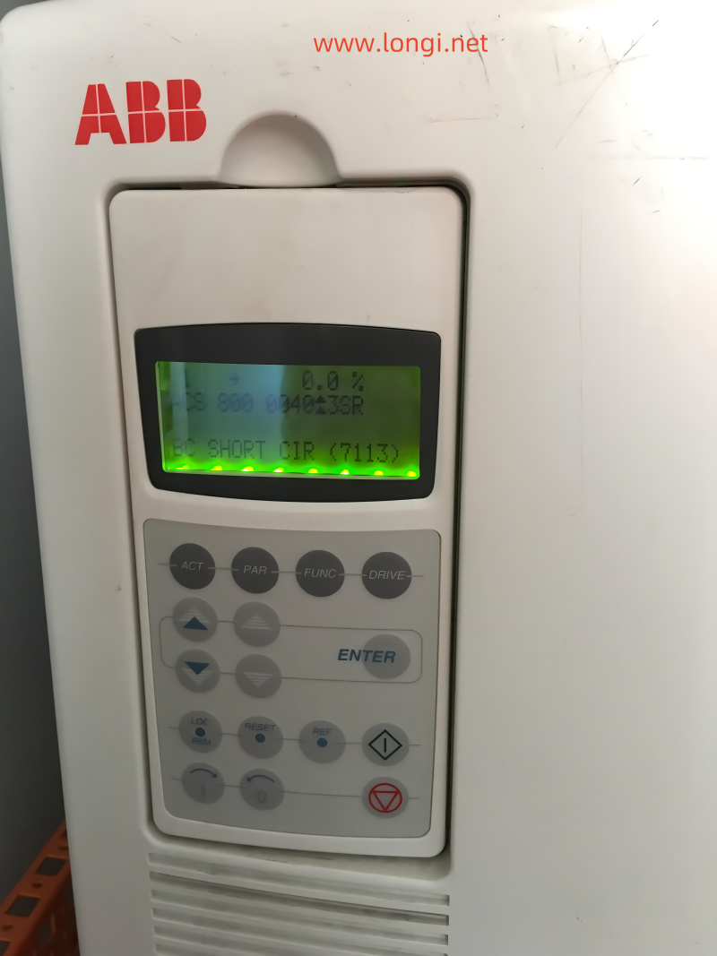
| BC SHORT CIR (7113) 3.17 FW 5 bit 2 |
Short circuit in brake chopper IGBT(s) | Replace brake chopper. Ensure brake resistor is connected and not damaged. |
| BRAKE ACKN (FF74) 3.15 FW 4 bit 3 |
Unexpected state of brake acknowledge signal | See parameter group 42 BRAKE CONTROL. Check connection of brake acknowledgement signal. |
| BR BROKEN (7110) 3.17 FW 5 bit 0 |
Brake resistor is not connected or it is damaged. Resistance rating of brake resistor is too high. |
Check resistor and resistor connection. Check that resistance rating meets specifications. See appropriate drive hardware manual. |
| FAULT | CAUSE | WHAT TO DO |
|---|---|---|
| BR OVERHEAT (7112) 3.17 FW 5 bit 3 |
Brake resistor overload | Let resistor cool down. Check parameter settings of resistor overload protection function (see parameter group 27 BRAKE CHOPPER). |
| Check that braking cycle meets allowed limits. | ||
| Check that drive supply AC voltage is not excessive. | ||
| BR WIRING (7111) 3.17 FW 5 bit 1 |
Wrong connection of brake resistor | Check resistor connection. Ensure brake resistor is not damaged. |
| CHOKE OTEMP (FF82) | Excessive temperature of drive output filter. Supervision is in use in step-up drives. | Let drive cool down. Check ambient temperature. |
| Check filter fan rotates in correct direction and air flows freely. | ||
| COMM MODULE (7510) 3.06 FW 2 bit 12 |
Cyclical communication between drive and master is lost. | Check status of fieldbus communication. See chapter Fieldbus control, or appropriate fieldbus adapter manual. |
| (programmable Fault Function 30.18, 30.19) | Check parameter settings: – group 51 COMM MODULE DATA (for fieldbus adapter), or |
|
| – group 52 STANDARD MODBUS (for Standard Modbus Link). | ||
| Check Fault Function parameters. | ||
| Check cable connections. | ||
| Check if master can communicate. | ||
| CTRL B TEMP (4110) 3.06 FW 2 bit 7 |
Control board temperature is above 88°C. | Check ambient conditions. Check air flow. Check main and additional cooling fans. |
| CURR MEAS (2211) | Current transformer failure in output current measurement circuit | Check current transformer connections to Main Circuit Interface Board, INT. |
| CUR UNBAL xx (2330) | Drive has detected excessive output current unbalance in inverter unit of several parallel connected inverter modules. This can be caused by external fault (earth fault, motor, motor cabling, etc.) or internal fault (damaged inverter component). xx (1…12) refers to inverter module number. | Check there are no power factor correction capacitors or surge absorbers in motor cable. |
| 3.05 FW 1 bit 4 and 4.01 | Check that there is no earth fault in motor or motor cables: | |
| (programmable Fault Function 30.17) | – measure insulation resistances of motor and motor cable. If no earth fault can be detected, contact your local ABB representative. |
|
| DC HIGH RUSH (FF80) | Drive supply voltage is excessive. When supply voltage is over 124% of unit voltage rating (415, 500 or 690 V), motor speed rushes to trip level (40% of nominal speed). | Check supply voltage level, drive rated voltage and allowed voltage range of drive. |
| FAULT | CAUSE | WHAT TO DO |
|---|---|---|
| DC OVERVOLT (3210) 3.05 FW 1 bit 2 |
Excessive intermediate circuit DC voltage. DC overvoltage trip limit is 1.3 × 1.35 × U1max, where U1max is maximum value of supply voltage range. For 400 V units, U1max is 415 V. For 500 V units, U1max is 500 V. For 690 V units, U1max is 690 V. Actual voltage in intermediate circuit corresponding to the supply voltage trip level is 728 V DC for 400 V units, 877 V DC for 500 V units, and 1210 V DC for 690 V units. |
Check that overvoltage controller is on (parameter 20.05). Check supply voltage for static or transient overvoltage. Check brake chopper and resistor (if used). Check deceleration time. Use coast-to-stop function (if applicable). Retrofit frequency converter with brake chopper and brake resistor. |
| DC UNDERVOLT (3220) 3.06 FW 2 bit 2 |
Intermediate circuit DC voltage is not sufficient due to missing supply voltage phase, blown fuse or rectifier bridge internal fault. DC undervoltage trip limit is 0.6 × 1.35 × U1min, where U1min is minimum value of supply voltage range. For 400 V and 500 V units, U1min is 380 V. For 690 V units, U1min is 525 V. Actual voltage in intermediate circuit corresponding to supply voltage trip level is 307 V DC for 400 V and 500 V units, and 425 V DC for 690 V units. |
Check main supply and fuses. |
| EARTH FAULT (2330) 3.05 FW 1 bit 4 (programmable Fault Function 30.17) |
Drive has detected load unbalance typically due to earth fault in motor or motor cable. | Check there are no power factor correction capacitors or surge absorbers in motor cable. Check that there is no earth fault in motor or motor cables: – measure insulation resistances of motor and motor cable. If no earth fault can be detected, contact your local ABB representative. |
| ENC CABLE (7310) 3.33 FW 6 bit 2 (programmable Fault Function 50.07) |
Pulse encoder phase signal is missing. | Check pulse encoder and its wiring. Check pulse encoder interface module and its wiring. |
| ENCODER A<>B (7302) | Pulse encoder phasing is wrong: Phase A is connected to terminal of phase B and vice versa. | Interchange connection of pulse encoder phases A and B. |
| ENCODER ERR (7301) 3.06 FW 2 bit 5 |
Communication fault between pulse encoder and pulse encoder interface module and between module and drive | Check pulse encoder and its wiring, pulse encoder interface module and its wiring and parameter group 50 ENCODER MODULE settings. |
| EXTERNAL FLT (9000) 3.06 FW 2 bit 8 (programmable Fault Function 30.03) |
Fault in external device. (This information is configured through one of programmable digital inputs.) | Check external devices for faults. Check parameter 30.03 EXTERNAL FAULT. |
| FAULT | CAUSE | WHAT TO DO |
|---|---|---|
| FORCED TRIP (FF8F) | Generic Drive Communication Profile trip command | See appropriate communication module manual. |
| GD DISABLED (FF53) | AGPS power supply of parallel connected R8i inverter module has been switched off during run. X (1…12) refers to inverter module number. | Check Prevention of Unexpected Start-up circuit. Replace AGPS board of R8i inverter module. |
| ID RUN FAIL (FF84) | Motor ID Run is not completed successfully. | Check maximum speed (parameter 20.02). It should be at least 80% of motor nominal speed (parameter 99.08). |
| IN CHOKE TEMP (FF81) 3.17 FW 5 bit 5 |
Excessive input choke temperature | Stop drive. Let it cool down. Check ambient temperature. Check that fan rotates in correct direction and air flows freely. |
| INT CONFIG (5410) 03.17 FW 5 bit 10 |
Number of inverter modules is not equal to original number of inverters. | Check status of inverters. See signal 04.01 FAULTED INT INFO. Check fibre optic cables between APBU and inverter modules. If Reduced Run function is used, remove faulted inverter module from main circuit and write number of remaining inverter modules into parameter 95.03 INT CONFIG USER. Reset drive. |
| INV DISABLED 03.17 FW 5 bit 7 (3200) |
Optional DC switch has opened while unit was running or start command was given. | Close DC switch. Check AFSC-0x Fuse Switch Controller unit. |
| INV OVERTEMP (4290) 3.17 FW 5 bit 13 |
Converter module temperature is excessive. | Check ambient temperature. If it exceeds 40°C, ensure that load current does not exceed derated load capacity of drive. See appropriate hardware manual. Check that ambient temperature setting is correct (parameter 95.10). Check converter module cooling air flow and fan operation. Cabinet installation: Check cabinet air inlet filters. Change when necessary. See appropriate hardware manual. Modules installed in cabinet by user: Check that cooling air circulation in cabinet has been prevented with air baffles. See module installation instructions. Check inside of cabinet and heatsink of converter module for dust pick-up. Clean when necessary. Reset and restart after problem is solved and let converter module cool down. |
| FAULT | CAUSE | WHAT TO DO |
|---|---|---|
| I/O COMM ERR (7000) 3.06 FW 2 bit 6 |
Communication error on control board, channel CH1 Electromagnetic interference |
Check connections of fibre optic cables on channel CH1. Check all I/O modules (if present) connected to channel CH1. Check for proper earthing of equipment. Check for highly emissive components nearby. |
| LINE CONV (FF51) | Fault on line side converter | Shift panel from motor side converter control board to line side converter control board. See line side converter manual for fault description. |
| MOD BOARD T (FF88) | Overtemperature in AINT board of inverter module. | Check inverter fan. Check ambient temperature. |
| MOD CHOKE T (FF89) | Overtemperature in choke of liquid cooled R8i inverter module. | Check inverter fan. Check ambient temperature. Check liquid cooling system. |
| MOTOR PHASE (FF56) 3.06 FW 2 bit 15 (programmable Fault Function 30.16) |
One of motor phases is lost due to fault in motor, motor cable, thermal relay (if used) or internal fault. | Check motor and motor cable. Check thermal relay (if used). Check Fault Function parameters. Disable this protection. |
| MOTOR STALL (7121) 3.06 FW 2 bit 14 (programmable Fault Function 30.10…30.12) |
Motor is operating in stall region due to e.g. excessive load or insufficient motor power. | Check motor load and drive ratings. Check Fault Function parameters. |
| MOTOR TEMP (4310) 3.05 FW 1 bit 6 (programmable Fault Function 30.04…30.09) |
Motor temperature is too high (or appears to be too high) due to excessive load, insufficient motor power, inadequate cooling or incorrect start-up data. | Check motor ratings and load. Check start-up data. Check Fault Function parameters. |
| MOTOR 1 TEMP (4312) 3.15 FW 4 bit 1 |
Measured motor temperature has exceeded fault limit set by parameter 35.03. | Check value of fault limit. Let motor cool down. Ensure proper motor cooling: Check cooling fan, clean cooling surfaces, etc. |
| MOTOR 2 TEMP (4313) 3.15 FW 4 bit 2 |
Measured motor temperature has exceeded fault limit set by parameter 35.06. | Check value of fault limit. Let motor cool down. Ensure proper motor cooling: Check cooling fan, clean cooling surfaces, etc. |
| NO MOT DATA (FF52) 3.06 FW 2 bit 1 |
Motor data is not given or motor data does not match with inverter data. | Check motor data parameters 99.04…99.09. |
| FAULT | CAUSE | WHAT TO DO |
|---|---|---|
| POWERF INV xx (3381) 3.17 FW 5 bit 9 and |
INT board powerfail in inverter unit of several parallel connected inverter modules. xx (1…12) refers to inverter module number. | Check that INT board power cable is connected. Check that POW board is working correctly. |
| 4.01 | Replace INT board. | |
| PPCC LINK (5210) 3.06 FW 2 bit 11 |
Fibre optic link to INT board is faulty. | Check fibre optic cables or galvanic link. With frame sizes R2-R6 link is galvanic. If RMIO is powered from external supply, ensure that supply is on. See parameter 16.09 CTRL BOARD SUPPLY. Check signal 03.19. Contact ABB representative if any of faults in signal 3.19 are active. |
| PPCC LINK xx | INT board fibre optic connection fault in inverter unit of several parallel connected inverter modules. xx refers to inverter module number. | Check connection from inverter module Main Circuit Interface Board, INT to PPCC Branching Unit, PBU. (Inverter module 1 is connected to PBU INT1 etc.) Check signal 03.19. Contact ABB representative if any of faults in signal 3.19 are active. |
| (5210) | ||
| 3.06 FW 2 bit 11 and | ||
| 4.01 | ||
| PP OVERLOAD (5482) 3.17 FW 5 bit 6 |
Excessive IGBT junction to case temperature. This fault protects IGBT(s) and it can be activated by short circuit at output of long motor cables. | Check motor cables. |
| SC INV xx y | Short circuit in inverter unit of several parallel | Check motor and motor cable. |
| (2340) 3.05 FW 1 bit 0, 4.01 |
connected inverter modules. xx (1…12) refers to inverter module number and y refers to phase (U, V, W). |
Check power semiconductors (IGBTs) of inverter module. |
| and 4.02 | ||
| SHORT CIRC | Short-circuit in motor cable(s) or motor | Check motor and motor cable. |
| (2340) | Check there are no power factor correction | |
| 3.05 FW 1 bit 0 and | capacitors or surge absorbers in motor cable. | |
| 4.02 | ||
| Output bridge of converter unit is faulty. | Contact ABB representative. | |
| SLOT OVERLAP (FF8A) | Two option modules have same connection interface selection. | Check connection interface selections in group 98 OPTION MODULES. |
| START INHIBI (FF7A) 3.03 bit 8 |
Safe torque off has been activated during motor run or motor start command has been given when Safe torque off is active. Or: Optional start inhibit hardware logic is activated. |
Close Safe torque off switch. If switch is closed and fault is still active, check power supply at ASTO board input terminals. Replace ASTO board. Or: Check start inhibit circuit (AGPS board). |
| SUPPLY PHASE (3130) 3.06 FW 2 bit 0 |
Intermediate circuit DC voltage is oscillating due to missing supply voltage phase, blown fuse or rectifier bridge internal fault. Trip occurs when DC voltage ripple is 13% of DC voltage. |
Check main supply fuses. Check for main supply imbalance. |
| FAULT | CAUSE | WHAT TO DO |
|---|---|---|
| TEMP DIF xx y (4380) 3.17 FW 5 bit 8 and 4.01 |
Excessive temperature difference between several parallel connected inverter modules. xx (1…12) refers to inverter module number and y refers to phase (U, V, W). | Check cooling fan. Replace fan. Check air filters. |
| Alarm is indicated when temperature difference is 15°C. Fault is indicated when temperature difference is 20°C | ||
| Excessive temperature can be caused e.g. by unequal current sharing between parallel connected inverters. | ||
| THERMAL MODE (FF50) | Motor thermal protection mode is set to DTC for high-power motor. | See parameter 30.05. |
| THERMISTOR (4311) | Motor temperature is excessive. Motor thermal protection mode selection is TEMP SENSOR. | Check motor ratings and load. Check start-up data. |
| 3.05 FW 1 bit 5 (programmable Fault Function 30.04…30.05) |
Check thermistor connections to digital input DI6. | |
| UNDERLOAD (FF6A) | Motor load is too low due to e.g. release mechanism in driven equipment. | Check for problem in driven equipment. Check Fault Function parameters. |
| 3.05 FW 1 bit 8 | ||
| (programmable Fault Function 30.13…30.15) | ||
| USER L CURVE (2312) 3.17 FW 5 bit 11 |
Integrated motor current has exceeded load curve defined by parameter group 72 USER LOAD CURVE. | Check parameter group 72 USER LOAD CURVE settings. After motor cooling time specified by parameter 72.20 LOAD COOLING TIME has elapsed, fault can be reset. |
| USER MACRO (FFA1) 3.07 SFW bit 1 |
No User Macro saved or file is defective. | Create User Macro. |
When encountering issues with your ACS800 inverter, it’s essential to follow proper troubleshooting procedures to address the problem effectively. Referencing the “ABB ACS800 troubleshooting manual” can provide invaluable guidance in diagnosing and resolving faults. Here are steps to handle ACS800 inverter faults:
- Identify the Fault Code: Upon encountering a fault, the ACS800 inverter typically displays a fault code on the panel display. Refer to the “ABB ACS800 troubleshooting manual” to interpret the specific fault code and understand its implications.
- Consult the Troubleshooting Manual: Once you’ve identified the fault code, consult the “ABB ACS800 troubleshooting manual” for detailed instructions on diagnosing and addressing the issue. The manual provides comprehensive troubleshooting procedures tailored to the ACS800 inverter’s specific components and functionalities.
- Follow Troubleshooting Steps: Follow the step-by-step troubleshooting steps outlined in the manual to systematically diagnose the fault. The manual offers insights into potential causes of the fault, along with recommended actions to resolve the issue promptly.
- Refer to Technical Support: In cases where troubleshooting efforts are unsuccessful or additional assistance is required, don’t hesitate to contact technical support. The “ABB ACS800 troubleshooting manual” serves as a valuable resource for technicians and support personnel, enabling them to provide informed assistance based on the specific fault encountered.
- Document and Learn: Throughout the troubleshooting process, document your observations, actions taken, and outcomes. This documentation can serve as a reference for future troubleshooting endeavors and contribute to continuous learning and improvement in managing ACS800 inverter faults.
By adhering to the guidance provided in the “ABB ACS800 troubleshooting manual” and following established troubleshooting procedures, you can effectively address faults encountered with your ACS800 inverter, minimizing downtime and ensuring optimal performance.