The mainstream servo motor position feedback components include incremental encoders, absolute encoders, rotary transformers, etc. The vector control of permanent magnet AC servo drive requires a position feedback component to provide the position information of the rotor D-axis of the permanent magnet motor to the servo driver. After the position feedback component is installed with the motor, it is necessary to obtain the position relationship between the rotor magnetic pole axis (D) axis and the motor A-phase axis through the position feedback component before the driver starts vector control. Taking an incremental photoelectric encoder as an example, the encoder provides the position increment and zero position Z signal information to the controller’s main control chip, and uses these three sets of signals to determine the motor position of the motor. In actual use, the incremental photoelectric encoder also provides three additional sets of UVW signals for roughly determining the initial position of the rotor D-axis during motor startup. The rising edge of the encoder U signal and the rising edge of the Z trigger signal are generally aligned. The problem is that when the encoder is installed on the motor shaft, it may be fixed at a certain position of 360 degrees relative to the motor A-phase axis (after the motor winding stator is assembled). If the angle at this position is not known, the position information of the D-axis of the motor rotor cannot be determined using the output signal of the incremental photoelectric encoder, and vector control of the motor cannot be completed. Therefore, it is necessary to obtain this position signal through certain adjustment methods, which can be called electrical angle phase initialization, encoder zero position adjustment or alignment.
The physical significance of the signals of incremental encoders and the concept of axis position of permanent magnet synchronous motors
1. The A-phase axis of the motor and the orientation of the magnetic field
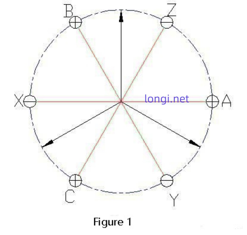
A permanent magnet motor is composed of three phase winding coils that are energized to form a rotating magnetic field, which is carried to the rotor poles equipped with rotor magnetic steel for rotation. The three phase windings form their own spatial magnetic potential vectors, and these three magnetic potentials combine to form a rotating magnetic potential vector: Figure 1 is a schematic diagram of the axial section layout of the motor winding. The A phase coil head is A-tail X, the B phase coil head is B-tail Y, and the C phase coil head is C-tail Z, connected in a star shape. XYZ is connected together, and the “+” and “-” in the ABC small circle represent the positive direction of the motor current of each phase equivalent coil (flowing from the beginning). When each phase coil is energized with a positive current, the arrows in the diagram are A and B according to the right-hand rule when the positive direction current is applied to the right hand direction. The direction of the magnetic potential (field) of A, B, and C when the positive direction current is applied to the three-phase coil, i.e. the respective axes of A, B, and C.
Assuming that when phase A flows in (positive direction) 1A, the current flowing out from phases B and C is -0.5A each (negative sign indicates opposite to the specified positive direction), as shown in Figure 2, the actual current at the coil edge of AZBXCY is+1+0.5-0.5-1-0.5+0.5 when unfolded counterclockwise along the cross-section. It can be seen that there are continuous positive current directions in the 180 degree electrical angle area along the circumference, and the other 180 continuous negative current directions are symmetrically distributed. The direction of the magnetic potential field determined by the right-hand rule in Figure 2 is the arrow direction shown in Figure 2, that is, the synthesized magnetic field is on the A-phase axis.
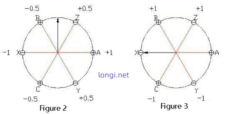
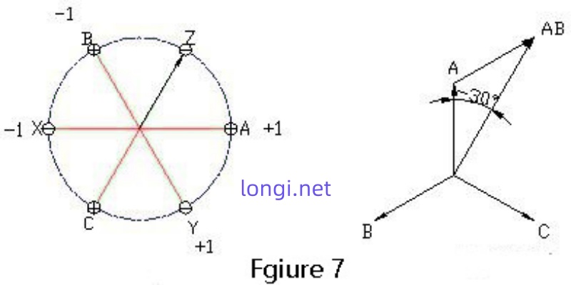
When powering on phases B and C, the current flows from phase B to phase C, as shown in Figure 3. The direction of the three-phase magnetic field is 90 degrees ahead of the axis of phase A.
2. The physical meaning of each output signal of the incremental photoelectric encoder
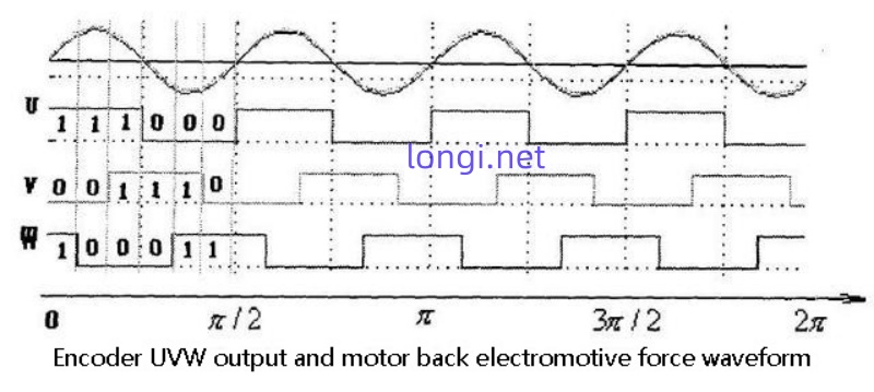
The commonly used incremental photoelectric encoder is a type of encoder with simple magnetic pole positioning function, which has two sets of output information: one set of information is A, B, Z; The other group is U, V, W, used to detect the position of magnetic poles, with absolute information function. Among them, A and B are basic signals, which can be processed to conveniently determine the direction and speed of motor rotation; Z pulses are used for reference positioning, with a phase difference of 120 degrees between the U, V, and W pulses. The number of pulses per revolution is consistent with the number of pole pairs of the motor. The use of U, V, and W signals can serve as a starting point for rough measurement of rotor position. After the motor starts, the precise angular position is obtained from signals A and B.
3. A deeper understanding of encoder output signals and motor position signals
A permanent magnet synchronous motor using an incremental photoelectric encoder as a position detection component must have its precise initial position measured when the system is first powered on. Because in the permanent magnet motor drive system, the position detection and initial positioning of the motor rotor are the basic conditions for system composition and operation, as well as the necessary conditions for vector control decoupling. Only when the rotor position of a permanent magnet synchronous motor can be accurately known, can the permanent magnet synchronous motor be equivalently transformed into an equivalent model on the dq coordinate system according to a series of equations in vector control. The system can control the permanent magnet synchronous motor using a control method similar to that of a separately excited DC motor, thus achieving the performance requirements of a servo transmission system composed of separately excited DC motors. In the driving system that uses an incremental photoelectric encoder to measure the position of the motor, the initial position of the motor needs to be detected first after the system is powered on. The initial position of the motor not only affects the positioning accuracy of the servo system, but also has a certain impact on the fast starting performance of the motor.
Taking a permanent magnet synchronous motor as an example, Figure 4 is the simplest diagram of the position relationship between the stator winding, magnetic steel, and HALL of the motor, with the rotor magnetic poles rotating uniformly counterclockwise. At the position shown in the diagram, the stator coil phase A crosses the zero point. If the DC brushless motor has a maximum output power when the current and back electromotive force are in the same phase due to 120 degrees conduction, and the U-phase voltage switch tube is delayed by 30 degrees of electrical angle conduction, the installation position of the HALL should be rotated counterclockwise over 30 degrees of electrical angle. The three sets of signal encoding outputs of the HALL output of a DC brushless motor reflect the motor position signal. The 360 degree electrical angle space is evenly divided into six consecutive spaces, each occupying 60 degrees of electrical angle.
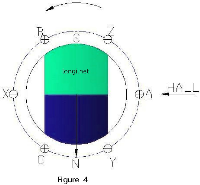
The UVW signal of the encoder is similar to the DC brushless HALL signal, so it can also play this role
What is the difference between the function and the HALL output signal? Three HALLs have been installed by
On the three-phase axis shown in Figure 1, the three-phase HALL output signal not only reflects the rotor position signal, but also
The information also includes the three-phase axis of the stator, so that the position information of the stator and rotor can be communicated
By matching with HALL, the angle and position information of the rotor relative to the stator axis can be found. When
After the encoder is installed, the UVW signal of the photoelectric encoder is input on the encoder disk
If a position sensor similar to HALL is placed on the encoder disk (actually
Similarly, when the zero position of the rotor magnetic potential (transition position between N and S poles) is rotated past this position
The U-phase signal of the photoelectric encoder undergoes a jump, and the rising edge of the U-phase signal can reflect the magnetic field of the rotor
The position of the polar axis (D-axis) triggers the rising edge of the Z-signal (encoder zero position) and the U-signal
The rising edge of the signal is consistent, so the Z trigger signal can reflect the position of the rotor’s D-axis at that time. The problem is,
The rising edge of the U-phase signal of the photoelectric encoder can reflect the position of the rotor magnetic pole axis (D-axis), when
The position of the rotor magnetic pole axis (D-axis) and the motor winding when the photoelectric encoder emits a Z signal pulse
The angle between the A-phase axes (compensation angle parameter in TI PMSM 3.1 routine QEP module)
The number is CalibratedAngle, but it needs to be converted to the pulse number of the photoelectric encoder.
4.Correction of the angle between the encoder Z signal and the motor A phase axis position
After the installation of the photoelectric encoder, when the rotor rotates, the position where the z signal is triggered may be in the range of
At a fixed angle of 360 degrees electrical angle with the A-phase axis of the motor as the reference zero point, so Compared to the HALL output signal, there is a missing link, which is the failure to phase the UVW signal with A Corresponding axes. This requires finding out this angle, which is usually achieved through the soft Correct the parts.
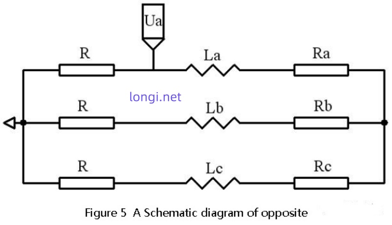
As shown in Figure 5, a two channel oscilloscope is used to observe the opposite potential of A and the contact of the encoder Z signal The time relationship of the generator position is determined by making the motor rotate at a constant speed and connecting three resistors with equal resistance values to form a star Then connect the three resistors connected in a star pattern to the UVW three-phase winding of the motor Line. In the figure, R is the external resistance, La, Lb, and Lc are the three-phase inductance of the motor stator, Ra Rb and Rc are the three-phase resistances of the motor stator, because the resistance of the motor stator is usually very small, as long as If the external resistance R is large enough, the stator resistance is ignored.
Use an oscilloscope to observe the output of motor A phase By focusing on the star type resistor, obtain the back electromotive force waveform of motor phase A.The period of the opposite electromotive force of motor A and the encoder Z signal and back electromotive force can be obtained from the oscilloscope The time difference between the zero crossing point of the waveform from low to high can be used to obtain the motor A phase axis and encoder Z signal
The angle difference of the number is:
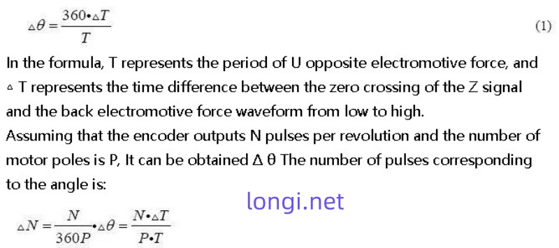
The period T of the opposite electromotive force from motor A and the waveform of the encoder Z signal and the back electromotive force from low to high The time difference between zero crossing can be used to calculate the corrected number of pulses, and the encoder zero can be corrected through software The phase relationship with the axis of stator A.
Installation of encoder and adjustment or alignment of encoder zero position
The above detailed description describes the method of correcting the angle between the encoder zero point and the stator A phase axis. In practice Many manufacturers in production directly align the zero point of the encoder when installing it, and the back electromotive force decreases from low to low There are two methods for crossing the zero point position: one is to cross the zero point from low to high with the opposite electromotive force of A Position alignment, another method is to align with the zero crossing point of the back electromotive force of the AB line from low to high.
1.Align the U-phase signal of the encoder (encoder zero point) with the zero point of the motor electrical angle A opposite to the zero crossing position of the electromotive force
a. Use a DC power source to apply a DC current smaller than the rated current to the UVW winding of the motor,
A in, BC out, as shown in Figure 2, orient the motor shaft to a balanced position;
b. Observe the U-phase signal and Z-signal of the encoder using an oscilloscope;
c. Adjust the relative position between the encoder shaft and the motor shaft;
d. While adjusting, observe the encoder U-phase signal jump edge and Z-signal until Z-signal
The signal is stable at a high level (where the normal state of the Z signal is low), and the encoder is locked
The relative position relationship with the motor;
e. Twist the motor shaft back and forth, and after letting go, if the motor shaft returns to the balance position freely each time,
If the Z signal can stabilize at a high level, then alignment is effective.
2.Align the U-phase signal of the encoder (encoder zero point) with the zero point of the motor electrical angle, i.e. the zero crossing position of the AB line back electromotive force
a. Apply a DC power supply to the AB winding of the motor with a DC current less than the rated current,
A in, B out, orient the motor shaft to a balanced position;
b. Observe the U-phase signal and Z-signal of the encoder using an oscilloscope;
c. Adjust the relative position between the encoder shaft and the motor shaft;
d. While adjusting, observe the encoder U-phase signal jump edge and Z-signal until Z-signal
The signal is stable at a high level (assuming that the normal state of the Z signal is low), locking the encoder and
The relative position relationship of the motor;
e. Twist the motor shaft back and forth, and after letting go, if the motor shaft returns to the balance position freely each time,
If the Z signal can stabilize at a high level, then alignment is effective